Samdim Design
Antonov AN-24RV
for FS 2004

Version 2.02
June 2005
Preface
When the
model An-24RV from RFGroup appeared for MS Flight Simulator 2000 it was like a
revolution in the add-ons design. Since, many simmers tried to adopt this model
for FS2002 but without much success. A new visual model and a new panel were
needed. After the release of our An-24B and even in spite of an incorrect
dynamics, this plane immediately replaced the old one. It has been followed by
two other planes of the same family: short-range transport An-26 and aerial
photographer An-30. The next release of An-24RV for FS2004 corrected some bugs
in An-24B, supplied a new dynamics and added lots of new features namely a full
interior with working virtual cockpit and passenger cabin.
The panel
update was a rather complicated deal because there had been almost no aircrafts
with the same panel. The aircraft itself has been declined in 43 modifications.
Each version could have a slightly different cockpit. With the development of
avionics, many gauges have been replaced on the existing panels. That's why it
is almost impossible to create "The An-24 Panel". We tried to make a
general panel that has the most used and typical avionics and instruments on
An-24. This panel is very complete because it includes also instruments used on
arctic and military versions.
In Version
2 of An-24RV all patches are included and several other changes were made also:
§
Even more realistic,
real turboprop flight dynamics
§
Thrust reverse is
replaced by propeller blade locking switch
§
New sound package
(still not proper however)
§
Enhanced light effects
§
Complete navigation
documentation and Navigator Notepad panel
§
COM radio and SPU
switch is adopted to frequency changes with VATSIM and IVAO clients
§
Passenger loader
application
The model
works in both FS2004 and FS2002. The panel works only in FS2004. There is an
older FS2002-compliant version available on the web.
Authors
|
Visual model, exterior and interior, animations |
|
Dimitri Samborski (samdim@chez.com) |
|
Exterior painting and many advices about the
cabin disposition and levers functionalities, model testing |
|
Nikolai Samsonov (instruktor@pisem.net) |
|
Interior painting, VC panel disposition,
beta-testing |
|
Maxim Mysin (mysinmax@mail.utk.ru) |
|
The panel itself (created in 3Dmax) and some
gauges |
|
Valery Bocharnikov (valery_b@ptline.ru) |
|
Gauges GAU and bitmaps to XML gauges,
technical support, testing and consulting |
|
Stepan Gritsevsky and Gabor Hrasko |
|
Flight dynamics |
|
Curl, Alexander Terentyev [Aless], Paul
[PI134]. Also thanks to Nick Sharmanzhinov [except], Alexander Timoshin
[UNKL], Alexander Zuev [ALZP] and Dmitry Kolesnik [TenderCat] |
|
Sound |
|
Based on package from Mike Maarse |
|
Passenger loader |
|
??? |
|
Documentation |
|
Gabor Hrasko (gabor@hrasko.com) |
|
Installation program |
|
Dimitri Samborski |
Thanks to
Serguei Skozhevnikov for his help in the development of the autopilot, to
Dmitry Ermakov for the complete An-24 instructions docs
Special
thanks to George Sukhykh for blueprints and testing, Vladimir Sokolov and
Dmitry Kolesnik for their XML gauges taken as example and to RFGroup -
Valentin, D.Prosko and others.
Thanks for
virtual airline Special Air Service Hungary active and former members - Zsolt
Baumann, István Szántai, György Posztos - for testing, documentations and for
all other support.
Recommended
RSBN scenery is from Andrei Pryadko.
The
Aircraft
Animations
The visual
model has some animations only accessible if you have shortcuts bounded
to the following actions (it can be configured in the Configuration/Key
Assignments menu) :
|
FS event |
Action |
|
Select exit - 1 |
open the
passenger door and deploy the ladder |
|
Select exit - 2 |
open the
cargo doors (front and rear). |
|
Tail hook up/down |
open the cabin windows |
|
Wing fold/unfold |
enter the
maintenance mode - open the gear bays, the engines, the nose and lower the
antistatic ground cable |
|
Water rudder up/down |
deploy glass cleaners |
|
Extend/Retract
Concorde nose & visor fully |
deploy landing/taxi lights |
The visual
model has every possible standard animations as follows.
Exterior model animations
|
Flaps |
|
Interior and exterior flaps deployment.
Interior flaps have little shields that open when the flaps start to deploy
(F5-F8). |
|
Control surfaces |
|
All control surfaces are animated and have
animated trims (joystick, num. pad. 1, 7, 0, Enter). |
|
Gears, rotating tires |
|
The tires image becomes blurred at high speed
to improve the visual effect. Extension/deployment (G) using13 animated parts
per gear. Working suspension. Nose gear direction independent from the rudder
(the rudder can be disabled by pressing Ctrl-D) |
|
Landing lights |
|
On An-24 landing lights share the same body
with taxi lights. To switch on the taxi lights, switch on navigation. Light
beams follow the lamp animation (bounded to gears retraction). Attention:
usual keyboard shortcuts (L, Ctrl-L) may not work with the panel. Use the
correspondent switches on the panel (bottom-left corner) |
|
Doors |
|
The passenger door (Shift-E) is supplied with
a folding ladder that deploys when the aircraft is on ground. There are also
two cargo doors (Shift-E 2) on the right side of the fuselage. Actually, all
the doors are bounded to the same key (passenger door) because of an
incompatibility of the cargo doors with the panel. |
|
Cabin windows |
|
open them after the landing to equilibrate
the air pressure. In the cockpit, they have also animated handles (bounded to
tail hook key). |
|
Gear bay doors, engine coverings and nose |
|
all animated for maintenance mode on ground.
There is also a little anti-static cable that descends to the ground (bounded
to wing folding). |
|
Propellers |
|
use each
three differently textured parts - for still, slow and fast rotation. They
dispose of the automatic feathering - it occurs when an engine stops airborne
(F1-F4). |
|
Glass cleaners |
|
they are
also visible from the cockpit (bounded to water rudder deploy). |
Cockpit animations
|
Throttle levers |
|
on the central console (F1-F4) |
|
Pedals |
|
joystick with Z-axis |
|
Flaps |
|
on the rear side of the central console. The
flaps switcher features a security mechanism with a locker (F5-F8). |
|
Gears |
|
on the rear side of the central console. Like
flaps switcher, features a locker (G). |
|
Parking brakes |
|
at the rear base of the central console and
beneath the captain's yoke (Ctrl-.). |
|
Yoke |
|
joystick |
|
Trims |
|
big wheels on both sides of the central
console - move very slowly (num.pad 1, 7). |
Cabin
windows and passenger door with ladder are animated like in the exterior model.
All the
exterior animations visible from inside the plane are present in the virtual
cockpit view.
The visual
model uses many materials with different levels of dynamic shine and
transparency. The exterior model uses reflective textures with alpha-channel
and lighting maps. The interior model uses night-lighting textures for the
interior parts. Some of the interior parts use also lighting maps.
The visual
model contains special instructions to hide invisible parts (like engines
interior when the engines are closed) and thus improve the frame-rate. There is
also a shadow model that makes the FS engine calculate the shadow far faster
and again improve the frame-rate on ground.
Virtual Cockpit
The plane
has a fully functional virtual cockpit with passenger cabin and exterior views.
Be sure you have the ActiveCamera plugin to be able to move inside the plane;
otherwise you can't enter the passenger cabin.
When you
are in the cabin, the disposition is the following:
- captain's place: as usually, to
the left
- 2nd pilot's place: as usually,
to the right
- navigator's place: behind the
captain
- radio's place: behind the 2nd
pilot, turned back
- flight engineer's place: in the
middle, behind the central console. His seat is folded and serves a stair
to access the pilots' seats.
Depending
on configuration and difficulty of flight conditions, the aircraft can be
piloted by smaller crew. Actually, only two to three people are needed to fly
the plane.
Behind you:
the passenger cabin. No first class, no economy class - everybody's equal in
the USSR.
Gears and
flaps controls are specific. The switches are provided with security lockers.
To raise the gears, you must first turn the locker, then initiate the
retraction with the switcher, raise the switcher to the initial position and
lock it again. The same procedure should be respected when operating the flaps.
These procedures are done automatically by animation.
The third
throttle lever operates the additional jet engine RU-19. Since a jet engine
cannot be placed on a turboprop aircraft (FS limitation), the lever is not operational.
In fact, it is rarely used in the real life.
The
navigator's panel is situated right behind the captain's place. Press
"2" on the numeric keypad to move back (using ActiveCamera) and see
the panel. A tip: when you move back, you'll first see a map or an approach
plan situated on the navigator's panel. Place here the approach plan of the
airport you are going to and you will have the possibility to quickly look at
it without loosing control of the aircraft. Just move backward and forward with
Active Camera. To place you own picture there, put the picture into the
Textures folder and name it A_MAP.bmp. Like any FS texture, it must be 256x256,
512x512 or 1024x1024 pixels and 8, 16 or 32 bit in depth. Grayscale (8 bits)
images would be the best. If the image doesn't show up in the cockpit, check it
isn't 24 bits in depth and is of a right dimension.
Flight
Instructions
Attention:
metric system. 100 kts =
Regimes for
engine AI-24:
|
Regime (mode) |
UPRT % |
|
Take off |
87-100 |
|
Nominal |
65 |
|
0.85 nom. |
52 |
|
0.7 nom. |
41 |
|
0.6 nom. |
34 |
|
0.4 nom. |
22 |
|
0.2 nom. |
12 |
Taxiing
Disengage
the parking brake, the slowly advance the power levers until UPRT is around
30%. Once the plane starts moving cut back the power to around UPRT 20-25% for
a taxi speed
Take-off and climbing
Flaps to
15° (third position).
Arm the
brakes, turn propeller lock ON and raise the throttle briefly to 40%. Then
raise to 100% and release the brakes (press "."). Start to
raise the plane at ~200 km/h, take off should be at ~220-
|
altitude (m) |
climb rate (m/s) |
|
0-2000 |
7.0 |
|
2000-3000 |
6.0 |
|
3000-4000 |
5.0 |
|
4000-5000 |
4.0 |
|
5000-6000 |
3.0 |
Cruising
Economic
cruising mode is UPRT 52% (0.85 nominal). The best economical flight altitude
is about
|
Altitude |
Altitude (feet) |
UPRT |
IAS |
IAS |
TAS |
|
5 000 |
16 400 |
52% |
330-340 |
172-178 |
440 |
|
6 000 |
19 700 |
52% |
320-330 |
172-178 |
460 |
Descending
Descending
mode is UPRT 20-30%. The alarm horn will be on below 38%. If bothers (I guess
yes), turn ЗВУК - sound alarms switch OFF on the
Engineer's panel. No speed brakes, so pay attention of speed.
Descend by
approximately 350-
The
critical speed for descending is
Landing
Keep speed
Critical parameters
Maximal
speed on descend:
Maximal
speed to deploy the gear:
Maximal
speed to deploy the flaps to 15°:
Maximal
speed to deploy the flaps to 38°:
Maximal
flight altitude:
Maximal
side-speed of wind: 12 m/c (22 kts)
Take off
distance: about
Landing
distance: about
Fuel calculation
(unit:
Fuel
consumption during cruising at altitude
Fuel for
taxi to line up and climbing to FL197 and descending from FL197, approach and
taxi to full stop:
Note that
climb to FL197 and descend from FL197 takes approximately
Example:
calculate necessary fuel for distance
- Estimate distance for cruising
flight:
- Estimate duration of cruising
at final flight level: 550/460 = 1.2 h
- Fuel needed for cruising
flight: 705 kg/h * 1.2 h =
- Total fuel needed for flight:
- Take
Grand
total:
The
Panel
Antonov
An-24 has a complex panel and normally it is piloted by a crew of four or five
members. It is impossible to put all their gauges on the same screen. In this
panel, we applied the principle of multiple workplaces. Our model can be
piloted by just one simmer who must take an appropriate workplace depending on
the stage of the flight. Each workplace corresponds roughly to the workplace of
a crew member. Some concessions have been made to simplify the use of all these
panels by one person but the gauges disposition is generally well respected.
Switching between panels.
Switching
between some panels can be done as usually by pressing Shift-1, Shift-2
etc. The others are shown/hidden by clicking special zones (buttons or active
icons) with the mouse. Shift key assignments are as follows:
|
Shift key |
Panel |
|
Shift-1 |
Flight Engineer's panel |
|
Shift-2 |
Autopilot |
|
Shift-3 |
Overhead panel |
|
Shift-4 |
SPU panel |
|
Shift-5 |
Navigator Notepad panel |
|
Shift-6 |
Joystick configuration service panel |
Panel
display order can not be easily controlled in FS2004. As both the pilot and the
navigator panels are large, they have to be the "bottom" panels if
you open other smaller panels, otherwise the smaller ones could not be seen. FS
defines panel stacking (order) based on opening sequence of the panels - i.e.
the one that was opened first will be at the background. Only first-time
opening is relevant. To make life even more difficult, some panels are
inter-dependent in our An-24RV. For example, the yoke is not needed to be shown
on the navigator panel, so it is closed when the user switches from pilot panel
to navigator panel. This provokes sometimes a malfunction: the impossibility to
show up some of the panels from the navigator panel.
In the
present version we tried to implement an automatic initialization process.
Uppon aircraft loading we close pilot panel, open navigator panel, close it,
and re-open pilot panel. This makes it sure that these panels will be displayed
behind all other smaller panels. This panel switching is fast and invisible,
but works quite reliable based on our test.
However if
you experience that this initialization is not working correctly for you - i.e.
smaller panels appear behind the navigator or pilot panels - perform the
following manual steps after aircraft loading:
- after the main panel loads,
switch to the navigator panel
- open and close the following
panels : autopilot, overhead (КУРС-МП)
and SPU
- switch back to the main panel
Pilot's panel
The main
panel is situated in the pilot cabin. The majority of the panels can be shown
from there.
The
autopilot panel is called by clicking on the icon
"АП-28Л" (low-right corner)
The weather
locator (a big screen at the right) is just a decorative element but it serves
to switch to the navigator panel. Click on it to show up the navigator panel.
Click on the weather locator in the navigator panel to go back to the main
panel.
Click in
the middle of the yoke to hide it. Click on its axis to show it up. There is
also a button on the yoke that calls the SPU panel. When the yoke is hidden,
the SPU panel can be shown by clicking on an icon close to the clock.
Above the
weather locator, there is an invisible button to show up the overhead panel
where all the radios are situated.

The main
panel contains the following gauges:
1.
Magnetic compass
2.
Indicator signals. The
middle and the right leds indicate a dangerous banking: more than 32° in the
nominal flight or more than 15° at takeoff or landing (the speed is lower than
3.
Pitch (left) and
vertical acceleration (right) indicator (AUASP)
4.
Combined horizontal
speed indicator ( КУС-730/1100К. ). Outer scale shows
IAS, inner scale shows TAS in km/h.
5.
Vertical speed
indicator (ВАР-30). Measures in meter/sec. 1m/sec =
180feet/min
6.
Indicator of dangerous
engine vibration. Doesn't work for the moment in FS2004.
7.
RSBN target signaling
lamps
8.
Markers lamp
9.
Control lamps for
"propeller unlocked" feature
10.
Propeller unlock
switch. Unlocking the prop diminish dramatically the thrust after touchdown. It
must not be switched off during flight.
11.
Artificial horizon
indicator. Switch it on from the flight engineer's panel.
12.
VOR/RSBN/ILS course and
glide-slope indicator (КППМ).
13.
Two-channel
RSBN/VOR/NDB bearing indicator.
14.
Throttle indicator (УПРТ-2)
15.
Engine indicators
ЭМИ-3К. Show the oil temperature and pressure together
with the fuel pressure before the injection.
16.
The dangerous altitude
panel (РВ-УМ). Signals when the altitude is lower than
the chosen one. Set the critical altitude with the tumbler on this panel.
Switch the monitoring on. "K" is a check-up position..
17.
Altitude indicator
(ВД-10). When the pressure is set, an additional gauge appears for
10 seconds. This gauge can also be shown by simply clicking on the altitude
indicator.
18.
Altitude (height) above
ground indicator (РВ-УМ). Monitoring should be switched
on at the dangerous altitude panel
19.
Fast alignment button
of the induction compass (ГИК - 1)
20.
Gyrocompass
(ГПК-52), it is also used to set up the course in the Turn
mode of the autopilot.
21.
RSBN aircraft bearing
and distance indicator (ППДА-П).
22.
Exhausting gas
temperature indicators (ИТГ-1), Scale is in x100°C.
23.
DME (measures in km
with one decimal) and DME 1-2 selector switch
24.
Pitot heating
25.
Landing/taxi lamps
deploy. Turn the switch off to hide/protect the lamps during cruise.
26.
Landing (up) and taxi
(down) lights. Middle position is off.
27.
Beacon lights
28.
Navigation lights
(red-green-white) and also panel lights
29.
Clock
(АЧС-1). Clicking on it will make the arrows disappear for 5
seconds. This is done to make easier reading the chronometer and the total
flight time.
30.
Flaps Indicator
31.
Gears indicator.
32.
Rpm indicator.
33.
Fuel level indicator
(main and auxiliary tanks). Needles show right and left tanks based on mode
switch (see next). Outer scale should be read if needles show total fuel, inner
scale is relevant for main or aux tank levels. Scale is in x100 kg. If tanks
are full, they hold 2 x
34.
Fuel level indicator
mode switch (off, total, main tanks or aux tanks).
35.
Not displayed. These
gauges are overlaid by Fuel level indicator and Fuel level indicator mode
switches. Fuel consumption indicators
(РТМС-1.2-Б1). Measures fuel consumption per
engines in x100 kg/h. The counter calculates remaining fuel based on
consumption. After refuel set this counter to the amount of fuel on left and
right tanks respectively. In this case during flight this counter should show
similar value than that of the Fuel level indicator (in total mode). Any
difference (most probably level indicator shows less then remaining consumption
indicator) suggests that you are loosing fuel somewhere (fuel is not consumed
only by the engines).
Panel
switches:
A.
Overhead panel switch
(above magnetic compass)
B.
Navigator panel switch
(on the weather radar screen)
C.
Flight engineer panel
switch (left to speed indicator)
D.
Yoke switch (on the
emblem of the yoke)
E.
SPU switch (on the
right horn of the yoke)
F.
Fuel level indicator -
Fuel consumption indicator toggle switch (left of trim wheel)
G.
Autopilot switch (right
of trim wheel)
Flight Engineer's panel
In reality,
there is no single flight engineer's panel on An-24. Instead, there are several
little panels that we have assembled in one to make it useful. It includes
three parts: engine startup (ЗАПУСК
ДВИГАТЕЛЕЙ), additional jet engine startup (ЗАПУСК
ДВ. "РУ-19" - not implemented) and power switches (АЗС).

Engines
start block:
36.
Start engine button
37.
Indicator of APD
(starter) system. Actually it is lit during the engines startup.
38.
Left-right engine start
selection switch. The middle position is neutral.
39.
Stop engine startup
button. Shuts down both engines.
40.
Fuel pump
("ПРТ-24") for the left engine.
41.
Fuel pump
("ПРТ-24") for the right engine.
Block of
fuses and switchers. Up position is "on", down position is
"off":
42.
АККУМ.
- accumulator switch;
43.
ГЕН.1,
ГЕН.2 - generator switches for the left and the right engines;
44.
ПТ-1000 -
avionics on switch;
45.
АГД-1
- horizon indicator switch;
46.
ГИК-1
- gyro-induction compass switch;
47.
СИГН.
ШАССИ - gears and flaps indicators on switch;
48.
РСБН
- RSBN navigation system switch;
49.
КУРС-МП
- Course indicator on switch;
50.
АП-28Л
- autopilot power on switch;
51.
ЗВУК
- sound alarms on switch;
52.
Propeller de-ice switch
and control lamp.
53.
Structural de-ice
switch and control lamp.
H.
Invisible button for
closing the panel.
Engines Startup
The engines
startup has been slightly simplified. It is done from the flight engineer's
panel. The procedure is the following:
- Accumulator switch on
(АККУМ)
- Left engine switch on
("ПРТ-24");
- Engine select switch
("ЛЕВ. - ПРАВ.") - to
the position Left ("ЛЕВ.");
- Press and hold the startup
button ("ЗАПУСК"), When the
engine reaches 5% of max RPM, the lamp
"РАБОТА
АПД" goes on, after reaching 45% the lamp goes off,
so you can release the button;
- Engine select switch
("ЛЕВ. - ПРАВ.") - to
the position Right ("ПРАВ.");
- Repeat the same startup
procedure for the right engine;
- Engine select switch
("ЛЕВ. - ПРАВ.") - to
the middle position;
- Turn on generator switches
(ГЕН.1, ГЕН.2) and turn off
Accumulator.
To stop an
engine, switch off the corresponding "ПРТ-24"
switch;
To stop
both engines, press the stop engines button
"Прекращение
запуска
двигателя".
The bottom
part of the panel is used to start the additional jet RU-
Overhead Panel
The
overhead panel contains mostly the standard radio-navigation stuff. On the real
plane, there are many other systems that cannot be implemented in FS2002-2004,
like fire extinction systems. We didn't put unusable gauges on the panel
because it is already quite overcrowded.

The
overhead panel contains the following gauges:
54.
Transponder
55.
Two duplicated sets of
NDB source frequency selectors. Upper pair is АРК1 lower pair
is АРК2. One can select between main and standby frequencies
by switches.
56.
Two sets of VOR/ILS
frequency selectors (VOR1, VOR2). No standby frequencies are available.
57.
NDB signal level
indicators
58.
COM1 panel with main
switch
59.
NDB and VOR system main
switches. VOR switch is the same as the one on the Engineer's panel.
60.
COM2 panel with main
switch
61.
Radio-system selector.
I.
Invisible button to
close the panel.
Detailed
description of these equipment can be found in the relevant navigation chapter.
Navigator's panel
Depending
on the modification, the navigator's panel in An-24 can vary from just a bottle
of oxygen to a complex system. We implemented here the most complete one, like
those used on arctic and military versions. Detailed description of these
equipment can be found in the relevant navigation chapter.

The
navigator's panel contains the following gauges:
62.
Two ADF panel. Same as
on overhead panel.
63.
ADF signal level
indicators. Same as on overhead panel.
64.
NAS-1 panel with main
switch, map angle and counter (Y, X, XY) gauges. This sub-panel overlays the
RSBN panel.
65.
Gyrocompass
ГПК-52 panel with alignment knob, main switch and latitude
selector
66.
Gyrocompass
(ГПК-52), it is also used to set up the course in the Turn
mode of the autopilot (same as on pilot's panel).
67.
NAS-1 Lateral Deviation
and Automatic Control gauge
68.
RSBN aircraft bearing
and distance indicator (ППДА-Ш). Higher
resolution (small needle) than that of the pilot's one.
69.
Radio compass source
selector switches.
70.
Two-channel ADF/VOR
indicator with correction ring
71.
ADF system switches
(same as on overhead panel)
72.
RSBN target indicator
lamps
73.
RSBN azimuth and
distance signal indicators
74.
Clock
АЧС-1.
75.
NAS-1 DISS (Doppler
radar) Slip Angle and Ground Speed indicator
76.
Gyro-induction compass
( ГИК-1) fast alignment button
77.
DME indicator and selector
switch.
The
following equipment are identical to the corresponding ones at the pilot's
panel and in fact shows the co-pilot panel as seen from the Navigator seat:
78.
RSBN target indicator
lamps
79.
Artificial horizon
indicator
80.
VOR/RSBN/ILS course and
glide-slope indicator (КППМ).
81.
Speed (IAS and TAS)
indicator
82.
Throttle indicator (УПРТ-2)
83.
Altitude indicator
(ВД-10)
84.
Vertical speed
indicator (ВАР-30)
85.
Pitot heating
86.
Landing/taxi lamps
deploy
87.
Landing and taxi lights
J.
Active icons for
opening/closing the following panels: autopilot, overhead
(КУРС-МП) panel, SPU, GIK-GPK gyro
alignment (ГИК/ГПК), RSBN (will overlay
with NAS), NAS.
K.
Active icon to switch
back to the Pilot's panel.
NAS and
RSBN panels are described in details in the relevant Navigation chapter.
Navigation
and communication systems
The
following chapters describe the An-24RV navigation and communication systems.
The RV variant of AN-24 planes were designed to perform special military and
arctic operations. These aircrafts are equipped with two enhanced RNAV systems:
the NAS-1 and the RSBN-2 systems. These systems are quite independent from each
other and are not highly integrated to the autopilot either. On some other
Russian aircrafts (for example the Tu-154) these and other systems form a
complex navigation system, making it very effective, but really difficult to
understand. The relatively simple NAS-1 and RSBN-2 systems makes AN24-RV an
ideal airplane to understand these systems in full depth.
Equipment
discussed in the following chapters include:
- Gyroscopes (gyrocompasses)
- NDB (ADF)
- VOR
- RSBN-2
- NAS-1
- Autopilot
The next
chapters starts from basic navigation principles and advances toward enhanced
equipment and tools. The RSBN-2 radio-navigation system can only be used over
the territory of the former Soviet union (if appropriate RSBN scenery is
installed), but the inertial NAS-1 system can be used anywhere on the Northern
Hemisphere (limitation is due to gyroscope correction mechanism).
Directions and courses
Magnetic versus true directions
If we try
to define our course we run into the problem whether to use magnetic or true
directions. In fact in most of the situations with standard planes in FS we use
magnetic directions. Runways are named by their magnetic direction, though it
generally does not make a big difference, as the last digit is left out from
the name anyhow, thus the small difference between magnetic and true heading is
not obvious. In Russia, in Northern Europe and in Canada however this
difference is quite important.
The
magnetic coordinate system has some drawback in some situations:
- Coordinates of geographic
locations (airfields, radio transmitters, cities…) are given as true
coordinates. If you calculate routes between such locations the result
comes in true directions. You have to keep in mind magnetic declination of
those points and transform the true courses to magnetic ones.
- The location of the magnetic
pole is not at all stable. It is wandering quite fast and you would find
several degrees of difference in magnetic declination data between charts
about the same areas form different years.
- On top of this magnetic field
of the Earth is not a nice dipole field; it is not as simple as of a
simple magnet rod resulting magnetic declination values changing in a
quite complex way along a latitude line.
- In Northern areas and near to
large metallic under ground stocks the declination could be so big that
the difference between magnetic and true directions would be confusing. If
you would like to fly towards the pole on a meridian it could be quite
confusing that the - magnetic - direction is 50 degrees (instead of 0
degrees), as this could happen for example in Canada.
- Special weather conditions
could result temporary changes in magnetic setup of a given area causing
the magnetic compass behaving unpredictable.
Because of
all of these issues you will find true coordinates rather important in
navigation of Russian aircrafts. They went so far that they even worked out a
navigation method without using the magnetic compass at all. We will see that
later.
Compasses and gyroscopes
A compass
is an equipment that could show you the direction to a certain point even if
you move from one place to the other. An obvious example is the magnetic
compass that points to the magnetic North Pole of the Earth. Another good
example is the radio-compass that points to the given radio transmitter. They
even put these two equipment together to form a radio-magnetic-compass (or
radio-magnetic-indicator RMI): the needle(s) of the RMI points to the radio
transmitter(s) while the ring of the equipment turns so that its top is
pointing to the magnetic heading of the aircraft.
Gyroscopes
on the other hand tend not to follow any movements. That is their duty - to
keep their original direction even if the aircraft is moving, turning or
bending. Using some methods you can align a gyroscope to a useful direction -
to magnetic North, to geographical (true) North or to your course - and it will
try to keep that direction later. It is important however that the direction
might become meaningless if you fly over longer distances as the gyro might
lose its direction relative to you. That is because the gyro keeps its
direction relative to the stars (Universe) and not to the Earth. This
could cause the gyro to loose its alignment even while staying on ground. As
Earth rotates 1 degree per 4 minutes (360 degrees per day) the gyroscope
performs a similar speed precession relative to the Earth (this precession is
simulated in FS if you check "gyro drift" in Realism Settings).
Several
type of correction mechanisms are used to keep the gyros aligned to the desired
direction. However in some cases it is an advantage that the gyro is not
totally "corrected". We will see this at the GPK gyroscope that is
showing the true or magnetic meridian direction of the take-off airport even if
we fly away long distances.
Loxodrome and the Great Circle
If you
maintain a specific heading (generally magnetic, but it could be true as well)
while flying long distance you will follow a specific course over Earth surface
called loxodrome. It is not a strait line at all (and if you fly long enough
you will end up at the magnetic North Pole with a spiral). By definition a
loxodrome is intersecting each meridians by the same angle. If you want to fly
from point P1 to point P2 than it is some dirty calculation to figure out what
should be the correct loxodrome and heading, but once it is done, navigation is
quite simple: just keep that (magnetic) course and you will end up at point P2.
If you want
to fly from P1 to P2 on the shortest route you have to fly on a great circle
course (orthodrome). Great circle is a circle defined by the intersection of
the surface of the Earth and any plane that passes through the center of the
Earth. There are infinite number of great circles on Earth - the Equator and
all the meridians are specific examples for that. For us a single great circle
is interesting; the one that goes through P1 and P2 points. Calculation of this
great circle is rather simple using spherical trigonometry, but navigating is
much more difficult. Great circles are intersecting the meridians by variable
angles because of meridian convergence. You have to start with a specific
course angle from P1, but along the course you have to change heading angle to
remain on the great circle. This is practically impossible to do using a
magnetic compass.
Great
Circle is the shortest route on a globe. Earth is not a perfect globe. Its form
is called geoid and on a geoid the shortest route is called geodesic and it is
rather difficult to calculate. Anyhow the difference between the geodesic and
the great circle is negligible in aviation.
Flying on the Great Circle (orthodrome)
Flying on
an orthodrome instead of a loxodrome has several advantages. The generally
known reason is that this is the shortest distance between any two points on
Earth. In fact this difference is quite small on middle latitudes and shorter
distances: on a
The other
advantage of the orthodrome relates to radio transmitter radials. These radials
are in fact orthodromes. If you would like to precisely follow a radial either
towards or from a beacon you have to fly on a great circle. As the range of
such transmitters are rarely larger than 300-
Orthodrome
(great circle) flights are supported by special gyroscopes. At point P1 you
spin the gyro, align it for example towards true North and you follow the
calculated start angle on the route. The gyro will not point to North any more
on the route (it will point to parallel of the meridian at P1 still), but it
does not matter. Just follow that initial course angle and you will arrive to
P2.

Figure 1 - On the Great Circle the course angle
(true or magnetic) is changing continuously
as you proceed from P1 to P2. You should maintain the angle relative to the
meridian at P1.
That is where a gyroscope will be handy.
If from point P2 you would like to continue to
point P3 on a great circle, you have to make some more trigonometry to
calculate the start angle from point P2. This angle is to be measured from the
meridian at P2. The problem is that our gyro is still aligned to the meridian
in point P1 and it is obviously not aligned with the meridian in point P2 as
the meridians are converging to the pole (that is why our start and
arrival angles differ).

Figure 2 - The course angle from waypoint P2 to
P3 should be adjusted
by the Fork angle that is a result of the convergence of the meridians.
We have two
options now:
- When flying over point P2 we
align the gyro to the meridian at P2 (as we did it at point P1 at the
beginning) and than read the new calculated start angle directly (again as
we did at point P1). You turn the plane to this new direction.
- We do not touch the gyro, but
we calculate the drift of our gyro that was cumulated from P1 to P2 due to
meridian convergence. This is called the fork (вилка in Russian) and it is basically
the difference of our start and arrival angles. We do not re-align our
gyro, but we add this fork angle to the calculated start angle from P2.
The resulting angle is still relative to the meridian at P1 and we can
read it from our gyro now.
Orthodromic
Course Angle 2 = Course Angle 2 + Fork 2
In Russian
terminology (see explanation later):
OZIPU2
= ZIPU2 + Δa2
We can
continue with either methods when we reach point P3. Russian navigation use(d)
this technics so much that they sometimes do not use magnetic compass at all.
Before take-off they align the aircraft along the runway precisely. The
magnetic direction and the declination of the runway is documented, so the true
heading of the aircraft can be calculated easily. They align the gyro to the
true North based on this and they follow the method described above along the
route. Near to the destination airport they make a similar calculation based on
the magnetic direction and declination of the runway, so keeping in mind the
calculated cumulative fork they are able to define the final turn.
In the
example above we aligned our gyro to true North (after calculating it form
magnetic direction and from magnetic declination of the runway), thus we used
true courses all along the route. If you prefer you might align the gyro to
magnetic North at the take-off runway and use magnetic courses on the route. In
this case however you should modify the above algorithm:
- Mathematical computations are
still give true courses between P1 and P2 (as the geographical coordinates
are based on the true coordinate system), thus you have to subtract
magnetic declination from this course when starting from point P1.
- If you do not want to re-align
your gyro at point P2, you have to calculate the fork as we did before.
However the fork at point P2 will have a second component (the first one
is because of meridian convergence as described above): the difference in
magnetic declination in P1 and in P2. You add this fork angle to the
calculated true start angle from P2.
It is
basically your decision whether to use magnetic or true courses. True courses
have the advantage that they are calculated directly from the equations and
they are independent of the spatial and temporal changes of magnetic
declination. Magnetic courses have the advantage that they are widely used in
charts, maps for example in SIDs and STARs and in ATC conversations.
VORs are
"advertising" magnetic courses (bearing), but their Russian
counterparts - RSBN beacons - use true courses. The complete RSBN-2 equipment
on AN-24 is built around true directions, thus it could be quite ambiguous to
align our gyro and define our courses relative to magnetic pole when we use RSBN. NAS-1 navigation system however
is independent of external systems, thus it can be used with any reference
directions.
Russian terminology
If you are
challenged enough to read Russian documents you will realize that they are
generally very precise in terminology. It is rather difficult to translate the
terms to English. In fact they are not frequently using the terms but
abbreviations instead. Hereby I summarize the most important terms.
The most
annoying thing is the different use of the term "course". In English
it means the track on which the aircraft is moving. May also mean the angle
("course angle") - the track's angle to the reference direction -
true or magnetic North. Thus we can speak about true and magnetic course. In
Russian the term "курс" (kurs) means "the angle
between the reference direction and the extended longitudinal axis of the aircraft"
- i.e. "heading"!
The Russian
equivalent of "course" is "путевой
угол" (track angle). The difference (angle) between the course and
heading is called "slip angle" ("угол
сноса") and is generally caused by cross-wind:
Course
= Heading + Slip
"Курс" (heading) is either
true ("Истинный курс,
ИК") or magnetic
("Магнитный курс, МК"). "Путевой
угол" (course) is also either true
("истинный
путевой угол, ИПУ")
or magnetic ("магнитный
путевой угол, МПУ").
If it is the planned (required) course than they call it
"заданный истинный
путевой угол, ЗИПУ" or "заданный магнитный
путевой угол, ЗМПУ" depending on the reference direction. And finally if the course
is measured relative to a reference meridian and not directly to the actual
meridian, then it is called as
"ортодромический
заданный истинный
путевой угол, ОЗИПУ" or
"ортодромический
заданный магнитный
путевой угол, ОЗМПУ" respectively:
ОЗИПУ = ЗИПУ + вилка
The course
referred frequently within this document - ZPU is the "planned
course" ("заданный
путевой угол, ЗПУ").
However when used in conjunction with the RSBN navigation it has a special
meaning: It is the course (angle) measured at the RSBN radio station between
the true meridian and the line going through the RSBN station parallel with the
"planned course" (see details later).
The Earth magnetic field
in FS9
The Earth
magnetic field can be described by the magnetic North vectors at each point on
the Earth surface. In practice magnetic declination used to be defined for each
location. FS stores global magnetic declination database in the
\Scenery\BASE\Scenery\magdec.bgl file. The database might be quite old (some
says it is from the early 80th, I did not check), but if you are not
using other external data, this will not cause any problem. FS stores a single
declination value for each 1 x 1 degree area. When defining declination for a
given location FS makes two dimensional linear interpolation. FS Navigator on
the other hand rounds the location coordinates (latitude and longitude as well)
to the nearest integer and uses a single value from the database thus in areas
where declination changes fast (near to the magnetic poles) it gives
practically useless magnetic courses. Use FS Flight Planner this case, or the
Route Planner provided with this document.
Sceneries
define magnetic declination to several individual objects as to airports, VORs,
NDBs, ISEC points etc. These might or might not match to the global declination
"below" them. However during navigation FS uses the global
declination table and adjusts aircraft equipment based on that only. It means
that magnetic compass or gyro-induction compass will show magnetic North based
on this table regardless of individual scenery elements' declination values.
The local (scenery-based) value has any role only in "aligning" the
scenery elements (runways, ILS beams etc.). Thus you have to care about it only
when turning to final generally. Anyhow we hope that scenery objects define
similar declination values than that of the global database ones.
Magnetic compass
 I think I do not have to introduce the magnetic
compass. It looks like a sphere on AN24-RV and you can find it at the pilot
panel at the right of the cockpit window. It is quite hard to read and you will
see that we will practically never use it.
I think I do not have to introduce the magnetic
compass. It looks like a sphere on AN24-RV and you can find it at the pilot
panel at the right of the cockpit window. It is quite hard to read and you will
see that we will practically never use it.
The
magnetic compass has a lot of problems on an airplane. It reacts slowly, then
it takes a long time to stabilize in the new direction. In steep turns it
simply hangs up. Even in a bit more moderate turn it is rather impossible to
judge when to come out off the turn based on the magnetic compass.
So I think
it is not worth speaking about it any longer…
The GIK gyro-induction compass
Gyro-induction
compass (Гиро-индукционный
компас, ГИК) is replacing the traditional magnetic compass in
most situations. It consists of a gyroscope that can be aligned to the magnetic
North using a specific device component (ИД -
индукционный
датчик). This component "scans" Earth's
magnetic lines of forces using a rotating induction coil. This way the gyro is
kept aligned to the magnetic lines of forces thus to the magnetic North Pole.
When switching on GIK you can speed up automatic alignment by pressing and
holding the "fast align GIK" button (right to the compass gauge):
alignment should happen within 20 seconds. During steep turns and larger
accelerations GIK might loose alignment; you might again align GIK with the
"fast align GIK" button. During normal flight operations the
induction circuit will make necessary corrections continuously and
automatically.
Using this
gyroscope to keep track of magnetic directions has some advantages over the
conventional magnetic compass. The gyro is much less sensitive for steep turns
and accelerations and it reacts faster.

Figure 3 - The gauge of the GIK compass with
two NDB/VOR needles (and with the corresponding selector switches) and with the
"fast align GIK" button
There are
several gauges linked to the GIK gyroscope, most important one is being the one
shown above from the navigator panel. Its inner scale is rotating and the
number at the top (signed with small arrow) shows the magnetic heading of the
aircraft. On the outer scale you can set a correction value for the correction
circuit (коррекционный
механизм -
КМ) between ±50°. The two needles of this gauge can be
connected to either NDB or VOR stations by the switches above (up = NDB, down =
VOR). The whole gauge can be seen as a sophisticated RMI (radio-magnetic
indicator or compass).

Figure 4 - The KPPM (left) and the RMI (right)
gauges
on the pilot panel are both using the GIK defined magnetic heading
The KPPM
gauge on both the pilot's and the navigator's panel shows the heading defined
by the GIK with a funny needle (circle with arrow). KPPM gauge receives corrected heading value from GIK. If
you set magnetic declination as correction value on GIK, KPPM will show true
heading instead of magnetic one. On the outer scale of KPPM you can set desired
course or heading.
The pilot's
RMI indicator shows the magnetic heading provided by the GIK. This heading is
not affected by the correction ring setting (at least not in the simulated
plane), so it always shows the magnetic heading! The outer scale is fixed and
shows bearings relative to the aircraft's longitudinal axis. The two needles
can show different transmitter combinations based on the bottom two switches.
The left switch (yellow needle) is 3-stage (RSBN/NDB1/VOR1) the right switch
(white double-line needle) is 2-stage (NDB2/VOR2). It is basically the same as
the navigator's RMI with the addition that is can also show RSBN bearing. In
many airplanes there is a dual ADF (NDB) indicator at the pilot only. This RMI
is built in to AN-26 planes mainly.
The
autopilot (introduced separately) can also use the signals of the GIK to
maintain the current magnetic heading (loxodrome course flying).
The GPK gyro-compass
GPK (Гирополукомпас, ГПК-52) serves course information for
several navigation subsystems. It is a separate gyroscope designed especially
to support flying on the Great Circle (orthodrome). This compass is designed to
correct precession and it keeps its direction relative to the meridian
(latitude line) of the point where alignment was made for a longer period. Its
configuration gauges can be found on the navigator's panel.

Figure 5 - GPK configuration panel. From left
to right: big "GIK-GPK align switch",
"power switch", "latitude selector" and the "GPK
indicator".
To
perfectly correct precession caused by Earth rotation the actual geographical
latitude (or an "average" latitude for a route segment) should be set
on the "Latitude Selector". Latitude can be modified during the
flight - it should be if latitude is changing several degrees. The power switch
also has to be turned on. At this point the gyro is spinning and is maintaining
its axis relative to the actual meridian (later called as reference meridian),
but it is not yet aligned to any specific meaningful direction.
As soon as
you turn the power switch on the small green airplane on the "GPK
indicator" rotates to an angle which is quite arbitrary. On the picture
above the gyro was initiated showing the aircraft heading as 115 degrees. It
means nothing as we had not defined a reference direction yet - we have to set
a meaningful value. You can turn the airplane figure to any meaningful degree
using the big knob (ЗАДАТЧИК
КУРСА) at the left. You can change alignment by 0,25 or by 2 degrees in any
directions depending on which area you click on the knob. In most cases you
align GPK to the magnetic heading provided by the GIK gyro (thus the two gyros
are aligned to each other), or to the true heading which is calculated using
the magnetic heading and the magnetic declination of the current location. To
make a more precise alignment you can invoke the GIK/GPK alignment panel
clicking on the "ГИК/ГПК"
(GIK/GPK) hot spot on the navigator panel.

Figure 6 - GPK-GIK gyro alignments. GIK is
already aligned with the magnetic compass and current magnetic heading of the
plane is 90 degrees as pointed by the red arrow.
A: Full alignment. GPK will provide course (OZMPU) relative to the magnetic
reference meridian.
B: GPK is aligned with a magnetic declination of 4 degrees. It will provide
course (OZIPU) relative to the true reference meridian.
C: GPK 0 degree is set to the current magnetic course, here to 90 degrees
(rarely used).
As you
will fly over long distances you will notice that the two gyros (GIK and GPK)
will lose their initial alignment. It has several reasons: it is mostly because
the moving airplane's relative position to the magnetic pole (pointed by GIK)
and to the initial meridian (GPK) will become different. You can re-align GPK
to GIK or to the true North again, but in certain cases it is not necessary or
even forbidden otherwise you lose your track. It all depends on what is
actually important to you. We will see it later.
The pilot has a same "GPK indicator"
gauge as the navigator has. The green airplane's nose always shows the heading
of the real aircraft based on the GPK. The whole "GPK indicator" ring
can be rotated using the knob on the left-bottom of the gauge. It is used to
execute automatic turns to the predefined GPK-based heading by the autopilot.
The degree on the top (pointed by a white small rectangle) shows the planned
direction after the turn. Autopilot will perform the turn if you select the
Turn mode on it (see later).
 The simulated GPK gyroscope can not
be used on the Southern hemisphere because Southern latitudes can not be set on
the GPK panel. In some other aircrafts there is a North/South switch attached
to the Latitude Selector, but that is missing in this version of An24 and
entered value is interpreted as Northern latitude. If wrong latitude is set,
precession correction will not work correctly and GPK gyro will lose its
alignment to the reference meridian rather fast (test it in FS!). The picture
on the right shows a simulated Il-18 aircraft's gyroscope panel; that consists
of a North/South (СЕВЕРН./ЮЖН.) switch above the Latitude Selector
(the other switch is the main-supplementary gyro selector).
The simulated GPK gyroscope can not
be used on the Southern hemisphere because Southern latitudes can not be set on
the GPK panel. In some other aircrafts there is a North/South switch attached
to the Latitude Selector, but that is missing in this version of An24 and
entered value is interpreted as Northern latitude. If wrong latitude is set,
precession correction will not work correctly and GPK gyro will lose its
alignment to the reference meridian rather fast (test it in FS!). The picture
on the right shows a simulated Il-18 aircraft's gyroscope panel; that consists
of a North/South (СЕВЕРН./ЮЖН.) switch above the Latitude Selector
(the other switch is the main-supplementary gyro selector).
Connection of the gyros to other equipment
At this
point it is interesting to compare AN24 gyroscope connections to that of other
aircrafts. One would see that in principle there is no real difference. In AN24
the systems are more separated thus didactically better to understand the
concepts behind.
AN24-RV gyroscope
connections
The two
gyroscopes are connected to other aircraft equipment in a rather
straightforward way. This is described in the picture below. It is important to
understand that GPK Indicator always shows direction based on the GPK gyro
alignment. The other RMI type of equipment show magnetic directions based on
the GIK gyro. The Dual ADF Indicator and the RSBN Bearing-Distance Indicator
(not shown on the picture) are not connected to either gyros, they show
radiomagnetic bearing relative to the aircraft horizontal axes or to the
meridian at the (RSBN) locator station.

Figure 7 - Connection of GPK and GIK gyroscopes
to various input and output devices. Pilot's RMI is not getting input through
the correction mechanism (KM) - at least not in the FS model.
Gyroscope connections on
other aircrafts (not An-24/26)
On some
other aircrafts there are no separate GIK and GPK gyros. There is a GPK gyro
only that has several work modes. On some aircrafts the gyros are duplicated
(Tu-154, Il-18) for reliability, accuracy and comfort. You can select via a
switch whether the main or the supplementary gyro should provide course
information to the different equipment. The gyros can work in different modes:
GPK
This is the "native" mode of the gyroscope without additional
correction mechanisms. Though these gyros are correcting several disturbing
effects (for example precession) on their own, they will slowly lose alignment
to the desired orthodromic direction due to minor configuration and
construction errors.
MK
Magnetic correction mode. In this mode the gyro is continuously adjusted by the
magnetic induction circuit ИД-2М (exactly like in case of GIK gyro on
AN) using also the correction value we set on КМ-4 for declination and for other deviations.
The gyro acts as a magnetic compass, but it is most reliable/robust than a
traditional compass. This mode is used to follow loxodromic courses or during
take-offs and landings, when magnetic directions are used and where there is no
difference between orthodromic and loxodromic courses due to short distances.
AK
Astronomical correction. In this mode the gyro is continuously adjusted by a
component like ДАК-ДБ-5 providing true
orthodromic course ( I have no information about how this component is exactly
working). In FS in most cases this is simply implemented as a very accurate
source for true direction. It is generally even independent of cloud coverage
and other blocking factors, so it is not very realistic (it is too good).
In most of
the cases modes for the individual gyros (main gyro and supplementary gyro) can
not be set totally independently. If the active gyro (that provides course info
to the other equipment) is in GPK or in AK mode, the other one is in MK mode.
If it is in MK mode, the other one is in GPK mode.
The gyro
also used to be adjusted either manually or automatically based on external
radio-station references. Generally the radio references have the priority and
when they are not available the system will use AK or MK mode whichever is
selected. Generally a warning will appear that radio-synchronization is not
available and the inertial correction systems are working. In deep turns or
during greater accelerations AK and MK correction is temporarily disconnected
from the gyro by
ВК-53РВ.
The Autopilot
The
autopilot (AP) of AN24-RV differs from what we could find in the Western
aircrafts. In fact there is a relatively small overlap between the
functionalities of the two types. Hereby I summarize briefly what this AP is
capable for and what not:
It CAN … |
It can NOT… |
|
maintain current altitude |
climb or descend to a specified altitude |
|
maintain the current pitch |
maintain a predefined vario |
|
turn with defined banking |
maintain a predefined speed (A/T) |
|
maintain heading based on GIK or GPK gyros |
follow a VOR or ILS radial (NAV) |
|
turn to a predefined heading based on GPK |
follow an ILS glide slope (APR) |
The great
minus is lack of auto-thrust and radial tracking. Both exist in some other
Russian aircrafts.
There is an
extra feature not listed here: the Automatic Control system of the NAS-1
system. It rather much differ from the general logic of AN24-RV autopilot and
is generally not built in to AN-24 planes. Based on my best knowledge it is
built in some specific purposed AN24-RVs. NAS-1 is an important component of
some other Russian aircraft's AP system and it is working correctly in the FS
AN24-RV. Its functions are discussed separately.

Figure 8 - The autopilot panel in AN24-RV
The AP can
be invoked by the Shift-2 combination or by clicking on the "АП-28Л" hotspots on either the
pilot's or the navigator's panel. The brief description of the components are
as below:
Russian |
English |
Description |
|
ПИТАНИЕ |
Power |
Power switch to turn on AP |
|
ГОТ |
Standby |
Yellow lamp indicating that AP is in standby mode. It will go on some seconds after you turn AP power switch on. |
|
ВКЛ АП |
Engage AP |
Button to engage AP once it is in standby mode. AP can be engaged in any conditions provided the altitude is greater than 300m, the pitch is between -20° and 20° and the bank is between -30° and 30°. |
|
ВКЛ |
On |
Green lamp indicating that AP is engaged and is controlling the plane. |
|
РАЗВОРОТ Л-П |
Turn L-R |
Coordinated turn to Left or to Right by the define banking. Click on the middle of the control to bring the plane back to straight flight fast. Scale is by 5 degrees up to 30 degrees banking. |
|
КВ |
Altitude corrector |
Button on the right turns
altitude corrector KB-11 on. |
|
ГОРИЗОНТ |
Bring to level flight |
Button bringing the plane to horizontal flight. This is not implemented, even the button is missing. In FS you can use КВ to perform the same action - though it is forbidden to do it in real plane. |
|
СПУСК - ПОДЪЕМ |
Descend - Climb |
Push and hold switch up to decrease pitch. Push and hold switch down to increase pitch. |
|
ГПК - ГМК - ЗК |
GPK - GMK - Turn |
3-stage mode selector switch: GPK: maintain current heading using GPK gyro GMK: maintain current heading using GIK gyro Turn: Turn to heading defined on the "GPK Indicator" |
|
АВТО ТРИММ |
Auto-trim |
Turn on the switch to let AP using the trim automatically. Turn off to manage the trim manually |
|
ТАНГАЖ |
Pitch |
Turn on the switch to let AP manage pitch Turn of to manage pitch manually |
|
ОТ СЕБЯ |
From you |
Lamp signs force on yoke from you is managed by the servo |
|
НА СЕБЯ |
Towards you |
Lamp signs force on yoke towards you is managed by the servo |
Regarding
RNAV the mode selector switch is the most important component of AP:
GPK
mode
The AP will maintain the actual heading (not course) based on the GPK gyro. The
aircraft will fly on a great circle if there is no drift (wind).
GMK
mode The AP
will maintain the actual heading (not course) based on the GIK gyro. The
aircraft will fly on a loxodrome if there is no drift (wind).
Turn
mode
The AP will perform a coordinated turn to the direction set on the GPK
Indicator gauge. The airplane will turn until the small green aircraft symbol
on the gauge will be vertical and point to the heading shown on the top. Do not
forget about wind drift when you define the target heading on the GPK
Indicator. After completing the turn switch the mode to either GPK or GMK mode
to maintain the heading! If you leave the mode as Turn, AP will turn back the
plane to the defined heading after you finish a manual or AP-based (РАЗВОРОТ
Л-П) turn.
This is generally not what you want and could be rather unexpected. You will
probably do not understand why the plane is turning back always.
"Turn
mode" can be effectively used when you are getting vectors during a STAR
(approach) procedure. As soon as you receive the instructions from the ATC, you
set the required heading on the GPK Indicator and switch on Turn mode. The
plane will perform turning to the new direction, you do not have to bother to
come out from the turn manually. Of course in this case GPK should be aligned
with GIK to work with magnetic direction as SID/STAR procedures and ATC are
defining magnetic courses. In case of frequent vector changes you might leave
AP in Turn mode so that you just have to modify direction on the GPK Indicator
and the plane starts turning immediately while you can read back the
instruction to the ATC.
There is a
separate Service Panel where one might further configure the AP. The full
description of that panel is out of the scope of this document, we mention
three parameters only:
Совм.управл
Combined control button. This is assigned to the 1st button (brake)
of the (1st) joystick by default. Pressing and holding the brake
button of the joystick while the AP is engaged will temporarily disengage AP
(green button goes off, yellow button goes on signing standby mode). You can
control the plane by the joystick and as soon as you release the brake button,
AP is taking back control maintaining the new pitch.
Быстр.
Откл
Fast disengage button. This is not assigned to any joystick buttons by default.
If you would like to disengage AP (go to standby mode) you have to either press
and hold brake button (but this only effective while you keep brake button
pressed), or you should turn off and on the AP main switch. Define a free
button of the joystick to this function here and then if you press this button,
AP will go to standby mode. You just press the button, you do not have to keep
it hold.
Вкл.АП
Engage button. This is not assigned to any joystick buttons by default. This
function is available by clicking on the ВКЛ АП button
on the AP panel. If you define a free joystick button for this function here,
it will be available from the joystick as well.
General
navigation and communication systems
General
navigation and communication systems include VOR/ILS, NDB (АРК) systems, transponder and COM radios. These
equipment are working the same way as in Western planes (and in default planes
of FS) and they are not described in details.
Radio
source selection
 The radio source selector on the
Course-MP panel is used to select the signal source (VOR1, VOR2 or RSBN) for
the gauges connected to the course system - KPPM and DME. The four red lamps
indicate missing (!) horizontal (Г1, Г2) and vertical (К1,
К2) direction beam of VOR1 and VOR2 respectively. Vertical beam signal
will be received in case of ILS beacons only.
The radio source selector on the
Course-MP panel is used to select the signal source (VOR1, VOR2 or RSBN) for
the gauges connected to the course system - KPPM and DME. The four red lamps
indicate missing (!) horizontal (Г1, Г2) and vertical (К1,
К2) direction beam of VOR1 and VOR2 respectively. Vertical beam signal
will be received in case of ILS beacons only.
KPPM gauges
of the pilot and the navigator can show signals from different sources. The
combination can be set by selecting one of the five options on the selector
switch:
|
Option |
KPPM at the pilot |
KPPM at the navigator |
|
РСБН |
RSBN |
RSBN |
|
РСБН/СП-50 |
RSBN |
VOR1 |
|
1 |
VOR1 |
VOR1 |
|
СОВМ |
VOR1 |
VOR2 |
|
2 |
VOR2 |
VOR2 |
This is
not working correctly on my installation. Navigator's KPPM shows always the
same as the pilot's one.
The
NDB (АРК) system
This system
is a standard NDB (non-directional beacon) system, sometimes called as ADF
(automatic direction finder). Frequencies can be set on the Course-MP panel.

Figure 9 - Dual ADF (NDB) indicator,
ADF/VOR/RSBN RMI for the pilot, ADF/VOR RMI for the navigator
The dual
ADF indicator is displaying NDB beacon bearings relative to the aircraft's
horizontal axis. The more complex RMI indicators are connected to the GIK gyro
and shows the navaid bearings relative to magnetic North, while the top of the
rotating ring shows actual magnetic heading of the aircraft. On the outer ring
of the navigator's RMI you can set a correction value for the GIK based
direction and it effects how courses appear on other equipment. However the RMI
on the pilot's panel is receiving non-corrected raw direction data from GIK.
The
Course-MP (VOR) system
This system
is a standard VOR/ILS navigation system developed originally for navigation
outside the Sovietunion. Nowadays VOR and ILS stations are widely used in the
area of former Sovietunion (CIS). Frequencies and bearings (radials) can be set
on the Course-MP panel.
Be careful
- unlike in the real plane - in the simulated AN-24RV you can not select TO and
FROM (inbound/outbound) directions. It is assuming always the logical one - do
not think in inbound or outbound only in direction. It will rarely cause
confusion. In case of ILS you do not have to select course at all. The course
system here always assumes TO mode and we can not use the ILS easily to
maintain runway heading for departure as we can not select back-course. You
might however use the ILS at the other end of the runway if back-course for that
ILS in the scenery is enabled.
KPPM is a
standard horizontal navigation and landing system displaying position of the
aircraft relative to the vertical (ILS only) and horizontal direction beams of
the VOR, ILS or RSBN system. Blinkers are closing upon receiving horizontal and
vertical direction signals.

Figure 10 - KPPM, ADF/VOR/RSBN RMI,
ADF/VOR RMI for the navigator, DME indicator
DME
indicator shows distance of the DME or VORDME station in kilometers with one
decimal digit (100m). Source can be selected by the switch at the top.
RMI
indicators for the navigator and for the pilot can show VOR station bearings.
The bearing is always magnetic.
Course-MP
system is connected to the GIK gyroscope and is using magnetic directions
always.
Listening
the Morse sign of the radio-stations
AN24-RV is
not equipped with a Morse decoder thus one should listen to the raw received
Morse signals to check whether the correct radio-station was tuned or not.
Selecting the correct source is quite difficult and involves several gauges.

Figure 11 - SPU panel and the VOR/NDB selector
On the SPU
aircraft intercom (СПУ - самолетное
переговорное
устройство) panel you should select RSBN,
NDB1/VOR1 or NDB2/VOR2. You select between NDB and VOR on the VOR/NDB selector
switches at the navigator panel above the large RMI indicator. These switches
select input for the RMI indicator as well. You also have to select
radio-source.
The
following table summarizes the settings of the various switches for listening
Morse signal of VOR1, VOR2, NDB1, NDB2 or RSBN stations:
|
Output |
SPU setting |
VOR/NDB selector |
Radio source selector |
NDB systems power*** |
|
VOR1 |
АРК1/VOR1 |
VOR1 |
1 or СОВМ* |
- |
|
VOR2 |
АРК2/VOR2 |
VOR2 |
СОВМ or 2 |
- |
|
NDB1 |
АРК1/VOR1 |
АРК1 |
- |
NDB2 should be off*** |
|
NDB2 |
АРК2/VOR2 |
АРК2 |
- |
NDB1 should be off*** |
|
RSBN |
РСБН-2С |
- |
РСБН or РСБН/СП-50** |
|
There
are some strange settings that are due to FS limitations, but also there could
be some bugs here as well:
*
In fact you can set 2 on the radio-source selector as well
**
In fact you can set 1 on the radio-source selector as well
***
If both NDB (АРК2) systems are switched on you will not hear
the Morse code even if all other switches are set correctly.
Morse codes
are as follows:
|
A |
.- |
G |
--. |
M |
-- |
S |
... |
Y |
-.-- |
4 |
....- |
|
B |
-... |
H |
.... |
N |
-. |
T |
- |
Z |
--.. |
5 |
..... |
|
C |
-.-. |
I |
.. |
O |
--- |
U |
..- |
0 |
----- |
6 |
-.... |
|
D |
-.. |
J |
.--- |
P |
.--. |
V |
...- |
1 |
.---- |
7 |
--... |
|
E |
. |
K |
-.- |
Q |
--.- |
W |
.--- |
2 |
..--- |
8 |
---.. |
|
F |
..-. |
L |
.-.. |
R |
.-. |
X |
-..- |
3 |
...-- |
9 |
----. |
Short-range Radio-navigation System (RSBN-2)
Introduction
Short-range radio-navigation system (РСБН - радиотехническая
система ближней
навигации) is a key component of RNAV
navigation on AN-24 and on other Russian aircrafts. It is similar to the VOR
system, but is expanded to support flights not directly going to or coming from
a radio-station, but to any points within the range of the system. Though it is
called "short-range" it is in fact longer range than VOR navigation.
Typical RSBN beacons has a range larger than
|
Altitude of aircraft (m) |
500 |
1 000 |
3 000 |
5 000 |
7 000 |
9 000 |
11 000 |
12 000 |
|
RSBN range (km) |
80 |
120 |
200 |
250 |
300 |
340 |
380 |
400 |
Accuracy of
the RSBN system is said to be slightly better than that of the VOR system.
Distance (orbit) is measured by the accuracy of ±200m, azimuth (bearing) is by
±0,25°. Stations are not selected based on frequency directly but based on
"channel number" (канал). Channels are assigned to
frequencies starting from 116.00 MHz (channel 1) stepping by 0.05 MHz up to
channel 40, frequency 117,95 MHz (1:116.00, 2:116.05, 3:116.10, …, 39:117.90,
40:117,95).
RSBN system
on the airplane continuously checks the position of the aircraft relative to
the beacon. Direction is relative to the RSBN station, i.e. it is measured
relative to the true (!) meridian going through the station, so it points from
the station to the airplane (or to the target). This is called azimuth and it
is not exactly the reverse direction (±180°) of the bearing to the station from
the aircraft. The difference is due to meridian convergence and it is equal to
the fork discussed in earlier chapter (in smaller distances the difference is
negligible) .
Work modes
RSBN is
supporting several work modes:
Azimuth TO
(АЗИМУТ
НА) The target is on the same RSBN radial we are flying, but its azimuth
(direction from the station) is just opposite. It means that the target is
right between the aircraft and the radio-station, so we have to fly TOWARDS the
station to reach is.
Azimuth FROM
(АЗИМУТ
ОТ) The target is on the same RSBN radial we are flying, and its azimuth
(direction from the station) is the same. The station is either behind us, or
it is ahead of us, but in this case the target is behind the station, so
finally we have to fly away FROM the station to reach it.
LEFT orbit
Supports flying what is called an anticlockwise DME-Arc in Western style
navigation. The radio-station is on your LEFT (ЛЕВО) side and you fly at a define
distance (orbit -
ОРБИТА) from it.
RIGHT orbit
Supports flying what is called an clockwise DME-Arc in Western style
navigation. The radio-station is on your RIGHT (ПРАВО) side and you fly at a define
distance (orbit) from it.
SRP
This mode (СРП) makes it possible to fly over a point that is
anywhere within the range of the radio-station. The point is defined by it's
azimuth and orbit. These data are referred as Target Angle
(УГОЛ ЦЕЛИ) and Target Distance
(РАССТОЯНИЕ
ДО ЦЕЛИ) in this case. The required course
(ЗПУ) should be defined also. This mode provides the greatest
freedom in flight, but has less accuracy.
Landing
Not supported in FS simulated AN24-RV. It has to be provided glide-slope
assistance beside vertical guidance similar that of ILS. It requires special
RSBN station and it is (was) used mainly in military aviation.

Figure 12 - Select mode FROM if your course and
azimuth are equal.
If they are opposite to each other, select mode TO. For all other cases select
mode SRP.
One has to
use special calculations to precisely define the appropriate parameters and
mode (the method is described later and a tool is provided separately). We have
to pick up the geographical coordinates of the starting waypoint (P1), the
target waypoint (P2) and of the RSBN station (PR). You can use either MS Flight
Simulator Map/Fight Planner or FS Navigator. We have to calculate the three
main parameters first:
Target
Angle
(УГОЛ ЦЕЛИ) is the true course
from the RSBN navaid (PR) to the target waypoint (P2).
Target
distance
(РАССТОЯНИЕ
ДО ЦЕЛИ) is the distance (in km) from the
RSBN navaid (PR) to the target waypoint (P2).
ZPU
(ЗПУ) is a virtual course angle measured at the RSBN navaid
(PR) on an orthodromy that is going through the navaid and that is parallel to
the orthodromy going from P1 to P2.
The most
important thing is that Course angle (ZPU) and target angle are both to be
measured at the RSBN station. Though the real course line and the helper line
going through the RSBN station are parallel, ZPU is not equal to the initial course
measured at point P1 (due to fork). Course angle is continuously changing while
flying from P1 to P2, but ZPU remains the same.
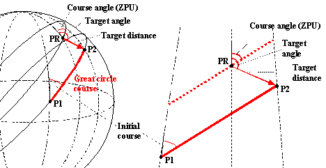
Figure 13 - Course angle (ZPU), target angle,
target distance and initial course (ZIPU) in the general SRP
mode of RSBN navigation from point P1 to point P2 if the RSBN navaid is at
point PR
If Target
Angle = ZPU then we have to fly away FROM the station. If Target Angle = ZPU ±
180 (reverse direction) then we have to fly TO the station. In other cases we
have to use the general SRP mode. In FROM and TO modes the system has a larger
accuracy and as there is a special relationship between Target Angle and ZPU
they use different names. ZPU is not used, Target Angle is called as Azimuth
and Target Distance is called as Orbita.

Figure 14 - Azimuth and orbita in the FROM mode
of RSBN navigation.
Initial course is not equal to Azimuth unless RSBN (PR) is placed at P1.
Setting RSBN parameters
RSBN
channel, mode and the calculated data should be set at the RSBN panel of the
navigator. Channel should be set on two switches: the upper switch defines the
tenths, the lower defines the remainder, so channel 34 should be set as 30 + 4
on the two switches.
In SRP mode
set the three values ZPU, Target angle and Target Distance at the right
sub-panel. In TO and FROM modes only the left sub-panel should be used to
define Azimuth and Orbita. It is worth to set these two values even in SRP mode
(Azimuth = Target Angle, Orbita = Target Distance) as the target signals (see
later) are bound to these settings. In case of LEFT ORBIT and RIGHT ORBIT modes
set only Orbita on the left panel to define the radius of the arc.

Figure 15 - RSBN panel to define (from left to
right) channel, mode,
azimuth, orbita, ZPU, target angle and target distance.
For
defining azimuth, orbita, ZPU, target angle and target distance you have to
click on the left side (decrease) and right side (increase) of the big knobs.
Clicking above the center will change the value by 10 degrees/km, below the
center by 0.1 degrees/km.
RSBN gauges used in navigation
The RSBN
system is not connected to the autopilot, thus it can not fly automatically the
defined route segment. The pilot and the navigator use three equipment to
manage the plane on the desired route:
RMI
indicator
is not frequently installed on An-24 planes, but mostly on An-26s. Its first
(yellow) needle can show either an RSBN, the first NDB or the first VOR station
bearing. The second (white) needle can show the second NDB or the second VOR
station defined on the CURS-MP panel. The selection can be made by two knobs at
the bottom of the gauge. The selected navaid type is displayed at the very
bottom. The RMI is connected to the GIK gyro and its bearing is always
magnetic!
Radio switcher
One should define the data source going to the gauges from the radio switcher
on the Radio Panel. It should be in the RSBN or in the RSBN-SP50 position (1st or 2nd)
to feed KPPM with RSBN data.
KPPM
is the gauge used to provide vertical and horizontal guidance with ILS, VOR or
with RSBN. Vertical guidance is provided only with ILS. The blinker at the
up-right quarter (marked with к) disappears
if there is a signal from the RSBN station.
PPDA
Aircraft bearing
and distance relative to the RSBN station. The thick needle shows the
ten-degrees on the outer scale. The thin needle shows degrees on the inner
scale. It is true (geographic) bearing and it is not the reverse of the bearing
to the RSBN station shown by the RMI. The difference is twofold: RMI shows
magnetic bearing, and there is a fork between the two locations (aircraft and
station). When aircraft bearing equals to Azimuth and distance equals to
Orbita, you had reached the target.
Signal
lamps
The lower two red lamps are on if there is no Azimuth (left) or Orbita (right)
signal from the RSBN station. They should go off if the signal is available.
The upper green lamp (left) is blinking if the target defined by Azimuth
and Orbita is within

Figure 16 - Main RSBN equipment for navigation:
radio signal selection switch,
KPPM ILS/VOR/RSBN indicator, ADF/VOR/RSBN RMI, PPDA, RSBN signal lamps
The marker
lamps are bounded to the Azimut and Orbita values so they should be defined on
the left sub-panel of the RSBN panel even if values are set on the right
sub-panel in SRP mode.
It has to
be emphasized that actual distance is measured on a strait line from the
aircraft in the air to the RSBN station so it is longer than the distance
measured on a map. Azimut, orbita and the other RSBN values are calculated
"on the map" independently from the flight altitude. This would cause
strange situations (bias) if orbita is less than 15-
In case of
larger distances the marker lamps provide quite accurate information. A plane
cruising by TAS =
RSBN navigation preparation
Before
starting to use any RSBN navigation features you have to perform the following
steps:
-
Check main avionics
power switch (ПТ-1000), GIK gyro power switch (ГИК-1) and RSBN power switch (РСБН) on the fuser (АЗС) panel.
-
Align GIK gyroscope
with magnetic North by pressing the Fast Align button.
-
Switch power on and set
latitude on GPK panel.
-
Align GPK gyroscope to
GIK (magnetic North) or to true North by using the magnetic declination of the
current place. Alignment to true North might be more convenient, as RSBN using
true coordinates for azimuth.
Basic RSBN navigation procedures
Main
challenges in RSBN navigation are 1/ the question of magnetic versus true
courses and 2/ the estimation of difference between starting and arrival
courses (fork). Do not forget that Azimuth, ZPU and Target angle should be
always defined as true courses! PPDA also shows current true bearing of the
plane. On the other hand KPPM shows magnetic heading (unless you set magnetic
declination on the navigator's RMI correction ring, but this is rarely done).
As a first
step in any navigation procedures you have to establish connection to the
selected RSBN station:
-
Define channel on RSBN
panel and check signal. Two bottom red RSBN signal lamps should not be on and
PPDA should show aircraft bearing and distance.
Flying
to the RSBN station on the shortest route
-
On the pilot's RMI
gauge switch to RSBN source on the first (yellow) needle and check bearing
(magnetic!) to the station.
-
Turn heading to the
station and adjust for wind.
This is
quite enough for reaching the station, though it is not very precise. If you
need more precise navigation, continue as follows:
-
Check aircraft
bearing (true) on PPDA. If the thin - high sensibility - needle is moving
clockwise (increasing bearing) then you have to adjust to the right. If it is
moving anticlockwise (decreasing bearing) you have to adjust to the left.
-
If the needle is
stabilized (your bearing from the station is not changing), then you are flying
exactly toward the RSBN station. Read the bearing value (both needles).
-
Set radio source switch
to RSBN and check signal on KPPM. Blinker к should be off. The horizontal
tracking indicator (vertical bar) should move from the center.
-
Set mode TO on the RSBN
panel.
-
Set exact bearing
copied from PPDA as Azimuth on the RSBN panel. The horizontal tracking bar
(vertical line) on the KPPM should be in the middle and should stay there.
-
Define Orbita as zero
or the distance of the target point if it is between you and the station (you
will not get the "target is within
-
Stabilize heading by
switching AP to GPK mode (or GMK on shorter distances). GPK should be switched
on and latitude should be set. Alignment mode (magnetic or true) is
indifferent.
-
Time-by-time check KPPM
tracking bar and wind drift indicator and adjust course if necessary.
The true
course to the station is approximately PPDA Azimuth ± 180°. The difference is
the fork between your current position and the RSBN station, because Azimuth is
calculated relative to the station. The difference is negligible in shorter
distances, but not in case of large distances.
Flying
to the RSBN station on a predefined radial
-
Set radio source switch
to RSBN and check signal on KPPM. Blinker к should be off. The horizontal
tracking indicator (vertical bar) should move from the center.
-
Set mode TO on the RSBN
panel.
-
Set inbound radial angle
± 180° as Azimuth. If magnetic radial is given, you have to add magnetic
declination at the RSBN station to get desired true radial (Attention: FS
Navigator defines declination with bad, opposite sign). This course will be
your arrival course, i.e. the course on which you arrive to the station.
-
Orbita is basically
indifferent. Set it to zero or to the distance of the target point if it is
between you and the station. Even if you fly to the station you might set
Orbita to the flying altitude (in km) instead of zero, otherwise you might not
get the "target is within
-
Check tracking bar
position on KPPM and navigate the plane toward the correct track.
-
When tracking bar is
closing to the middle, you are to be reaching the track. Turn towards the
station and maintain the course by keeping tracking bar in the middle. Adjust
for crosswind.
-
To determine course
deviation before tracking bar actually moves from centre check aircraft
bearing (true) on PPDA. If the thin - high sensibility - needle is moving
clockwise (increasing bearing) then you have to adjust to the right. If it is
moving anticlockwise (decreasing bearing) you have to adjust to the left.
-
Stabilize heading by
switching AP to GPK mode (or GMK on shorter distances). GPK should be switched
on and latitude should be set. Alignment mode (magnetic or true) is
indifferent.
-
Time-by-time check KPPM
tracking bar and wind drift indicator and adjust course if necessary.
Flying
from the RSBN station on a predefined radial
This is
nearly the same procedure than to fly to the RSBN station on the predefined
course. The main difference are as follows:
-
Set outbound radial
angle as Azimuth.
-
Set FROM mode on the RSBN
panel.
-
Orbita is basically
indifferent. Set it to zero or to the destination of the target if it is on the
outbound radial.
Flying
to point P2 on the shortest route
If the
coordinates of point P2 are not yet defined by their azimuth and orbita (in
this case they are called as target angle and target distance) then perform the
following steps:
-
Pick up the
geographical coordinates of point P2 and of the RSBN station (PR) as well from
FS Map or from FS Navigator.
-
Calculate RSBN data
(see the Route Planner provided with this document)
Next steps
are common regardless of source of the coordinates:
-
Set SRP mode, Target
angle and Target distance. Set Azimuth and Orbita also to provide input for the
signal lamps.
-
Set radio source switch
to RSBN and check signal on KPPM. Blinker к should be off. The horizontal
tracking indicator (vertical bar) should move from the center.
-
Change ZPU until KPPM
tracking bar moves to the middle position. Be careful: there will be two
matching angles opposite to each other. You have to have a general idea on the
direction of point P2 to select the correct one. Selecting the wrong angle
would result to the "back course" type of reverse behavior of KPPM
tracking bar.
-
Turn the plane to the
direction of the course. The rough true (!) course will be equal to ZPU, the
bias being the - not calculated - fork between your position and the RSBN
station. Define heading keeping in mind cross wind.
-
You might double-check
yourself based on FS Navigator. Move the mouse cursor over the destination (P2)
object (NDB, ISEC point, custom waypoint, airport etc.). An info-box should
appear and the second line from the bottom will show "Fly to course".
This is the correct magnetic (!) course you should select at your current
position. Set heading keeping mind cross wind.
-
Set AP mode to GPK. GMK
mode can be used for shorter distances only.
-
Adjust and follow track
based on KPPM signal. Keep track of cross wind.
Flying
to point P2 on a predefined course
This is a
rather complex process and in most of the cases can be defined as flying from
point P1 to point P2. Perhaps the plane will join the P1 - P2 segment somewhere
in the middle only, but it is not a real difference.
Flying
from point P1 to point P2
-
Pick up the
geographical coordinates of the two points and of the RSBN station (PR) as well
from FS Map or from FS Navigator.
-
Calculate RSBN
navigation data (see the Route Planner provided with this document)
-
Calculate true or
magnetic start course with Route Planner.
-
Define mode and set all
relevant data on the RSBN panel. Set azimuth and orbita even in SRP mode to
provide input for the signal lamps.
-
Set radio source switch
to RSBN and check signal on KPPM. Blinker к should be off. The horizontal
tracking indicator (vertical bar) should move from the center.
-
Check GPK latitude
setting and GIK/GPK gyroscope alignments.
-
Set Auto-pilot (AP)
mode to GMK or GPK.
-
Prepare initial course
(adjusted by cross wind slip) on the GPK Turn Indicator.
-
When approaching point
P1 the horizontal indicator bar on KPPM should be moving to middle position.
-
At this point or a bit
before (depending on turn angle) switch AP to Turn mode, or perform the turn
manually.
-
Set AP mode to GPK (as
the radial defines an orthodrome). GMK mode can be used for shorter distances
only.
-
Adjust and follow track
based on KPPM signal. Keep track of cross wind.
If initial
heading is set correctly and is maintained by GPK and if crosswind is not
changing then the plane will follow the track to point P2. In realistic
situations however track should be checked on KPPM time-by-time and heading
should be adjusted. Bias is originated from the following reasons: not
absolutely precise initial heading setting; GPK gyro alignment errors; cross
wind change.
Autonomous Navigation System (NAS-1)
Introduction
NAS-1
(НАС-1, Навигационная
автономная
система) is an autonomous system in a sense that is
does not require any external radio signal transmitters to keep track of
aircraft route. It is using a Doppler radar equipment DISS
(ДИСС, доплеровского
измерителя
путевой
скорости и
угла сноса) that is emitting radio signals and
checking mirrored waves. It measures aircraft speed (TAS) and also slip (course
and heading difference) generally caused by cross wind. Accuracy is 0.5% for
speed and ±20' for slip measurement.
With the
help of the GPK gyroscope NAS keeps track of the movement of the plane and
updates its coordinates in a Cartesian (X-Y) coordinate system. It is even
capable of drive the plane along a predefined course - and compensating wind! -
via the Automatic Control system SAU (САУ,
системы
автоматического
управления) which
is connected to the lateral control channel of the autopilot.

Figure 17 - We generally keep track of aircraft
position as distance on route and
lateral deviation from route, but there are other options as well.
The NAS-1 gauges
Main
controls of the NAS system can be reached from the navigator's seat. The main
NAS panel will overlay the RSBN panel.

Figure 18 - NAS-1 control equipment with
hot-spots: Map angle selection gauge, Counter switch, Cartesian coordinates
counters (Y, X and YX counters), Reset All Counters icon,
Speed/Slip counter and Lateral Deviation/Automatic Control gauge.
Counter switch
turns on aircraft co-ordinates tracking. All other NAS functions are working
even if this switch is off.
Map angle
Here you can define the direction of the coordinate axis "C" (Y)
relative to the reference direction defined by the GPK gyroscope. This is
generally true North, magnetic North or the actual route segment course.
Plane coordinates The
two needles of this gauge shows aircraft coordinates relative to the reference
point (where the gauge was reset or set manually). Needle "C" is
named by North (Север), needle "B" is by East (Восток). You can consider them as
coordinates Y and X respectively. Coordinates are given as 10 km-s from the
reference point in Y and X directions. The additional counter at the top shows
1000 kms.
Y coordinate
X coordinate
These two additional gauges show Y and X coordinates from the reference point
in
Reset
coordinates Clicking on this hotspot (right-bottom of
panel) will reset all counters at once.
Speed/slip
counter displays aircraft speed (TAS) and slip as reported by DISS Doppler radar
equipment.
Lateral Deviation On
this gauge (ЛБУ,
линейное
боковое
уклонение) you can define
the known lateral deviation (in km) of the plane relative to the desired route.
Set deviation on the knob at the right (in
Coordinate
counters can be reset by clicking at the centre of the gauge by the mouse. The
four values ("B" and "C" on the default counter,
"B" on the "B" counter and "C" on the
"C" counter) can be reset individually. To reset all counters at once
click on the hotspot below the CB counter.
Map angle
and aircraft coordinate counter
NAS-1 is
keeping track of aircraft movement using the DISS Doppler radar. Raw result is
shown by the speed and slip gauge. Using the GPK gyroscope axis as reference
direction NAS-1 keeps track of aircraft coordinates in a Cartesian coordinate
system Y axis being the direction defined by GPK and X axis being the
perpendicular direction. The axes are called as "C" and "B"
(Север and Восток). Coordinate units are kilometers
(meters on the high resolution gauges). Y axis points toward either true North
or to magnetic North depending on GPK gyro alignment.
The
coordinate counters are set to the desired value (generally zero) at a
reference point whose real geographical coordinates are known. When the plane
flies over the point you turn the counter switch on and coordinate tracking
starts. Alternatively you reset the counters when flying over the reference
point.

Figure 19 - Aircraft coordinates can be read
from the two needles of the counter gauge
as distances from the reference point toward North (C) and East (B) directions.
During
aircraft navigation it is generally more natural for the pilot and for the
navigator to see the coordinates as distance on route and lateral deviation
from route. This is possible by rotating the coordinate system (map) to the
route course. This angle is called as Map angle (угол
карты) and can be set by a special gauge with a
resolution of 0.25°. Map angle is measured relative to true or magnetic North
whichever is defined by GPK.
This
coordinate system makes it possible for NAS-1 system to send control signals to
the Autopilot system. The lateral channel of AP will receive route deviation
information and will maintain the aircraft on the desired route (see next
chapter).

Figure 20 - The coordinate system is rotated
towards the route course, thus Y and X ("C" and "B")
coordinates show distance on route and lateral deviation from route
respectively.
Automatic control and lateral deviation
Automatic
Control (САУ,
система
автоматического
управления) is a
special function of NAS-1. It is able to send signals to the horizontal channel
of the autopilot, thus it is able to navigate the plane horizontally. It sends
signals to the AP based on the calculated lateral deviation. Deviation is started
calculating relative to the course defined by map angle as soon as Automatic
Control is turned on. Map angle is relative to the alignment of the GPK gyro
and movement is measured by the DISS Doppler equipment.
Turn on
Automatic Control by pressing the left button on the Lateral Deviation control.
The green lamp at the bottom will go on and the lateral channel of the
autopilot will be controlled to keep lateral deviation zero. The coordinate
Counter switch setting has no effect on the operation of the Automatic Control.
If the
current course is not parallel with the Y ("C") coordinate of the map
(map angle) when you turn on Automatic Control or if you manually change map
angle (you rotate Y axis) while Automatic Control is on, then the plane will
maintain a coordinated turn to align to the new Y axis. As turn can not be made
in place, while turning it will gather some lateral deviation thus Automatic
Control will overturn and bring back the plane to zero deviation.
If you
manually set lateral deviation while Automatic Control is on, or if it is not
zero when Automatic Control is turned on, then the plane will perform
coordinated turns and passes over a parallel route where lateral deviation is
zero.
Autopilot
should be on to work with Automatic Control. AP can work in any modes,
practically either in GPK or Turn modes. Switching from GPK to Turn mode
however will turn off Automatic Control. While in Turn mode turning Automatic
Control on will suspend (!) Turn mode, but it will be reactivated as soon as you
turn off Automatic Control. It is a good practice to set back mode from Turn to
GPK while flying under Automatic Control to avoid unwanted effect when turning
the control off.
Rotating
the Turn (banking) Knob ("РАЗВОРОТ") will also switch off
Automatic Control. Automatic Control can not be switched on while Turn knob is
not in neutral position. This means that when we would like to effectively
combine Automatic Control with turns, we have to use GPK Indicator to perform
the turn instead of the Turn knob.
Basic NAS navigation procedures
NAS is a
complex system providing information on aircraft speed, slip, aircraft
coordinates and lateral deviation from desired route. It can also control the
lateral channel of the Autopilot. It can be used in a variety of situations in
aircraft navigation.
NAS system
is using the GPK gyroscope for keeping track map axes. You have to prepare GPK
gyro before using NAS:
-
Turn on main GPK
switch, set average route latitude and align the gyro with any meaningful
direction. It is generally GIK (magnetic North) or true North.
Keeping
track of cross wind
Cross wind
causes the plane deviate from its desired course. You must turn a bit toward
the direction of the wind and slip the plane to remain on track. The required
slip angle depends on wind speed and direction. NAS Doppler radar system keeps
track of slip which is generally caused by cross wind and displays it as
degrees of slip. Positive (right) slip should be compensated by a similar
amount of decrease (left) in aircraft heading and vice versa. If desired course
is 40° and slip is +7° then heading should be 33°.
It should
be noted that wind direction and speed information is not directly available.
-
Turn the plane heading
toward the desired heading.
-
Check slip angle,
deduct it from the desired heading and adjust heading
-
In case of larger slip
the heading correction might effect the slip, so you might have to retune
heading again.
-
Time-by-time check slip
and correct heading.
Flying from point P1 to
point P2
Hereby we
assume that point P1 is the initial waypoint of the route right after taking
off. We also assume that you will be able to detect when flying over point P1.
It is wise to use an NDB, VOR or RSBN station around the take-off airport as
first route waypoint.
-
Pick up the
geographical coordinates of the two points from FS Map or from FS Navigator.
-
Calculate NAS
navigation data (see the Route Planner provided with this document)
-
Check and turn off NAS
Counter switch.
-
Reset all coordinate
counters (check high resolution counters as well). Be sure that Lateral
Deviation control is reset as well.
-
Set initial course
segment as Map Angle.
-
If you would like to
use Automatic Control, then turn Autopilot on and set mode to GPK.
-
When flying over point
P1 turn NAS Counter switch on. You might turn Automatic Control as well.
Correcting lateral deviation
In spite of
its good precision NAS system will collect a relevant amount of bias during
longer journeys. That's why it is a good practice to check correct aircraft
position based on external references whenever it is possible. You should make
a note on the bias of both coordinates and perform necessary correction. Bias
on the Y coordinate ("C") does not effect current course, but on the
X coordinate ("B") it does.
To make the
manually correction when Automatic Control is off, follow the next steps:
-
Calculate lateral
deviation from the desired track using external information (visual, radio
signals etc.).
-
Make sure NAS Counter switch is on.
-
Switch to the high
resolution X coordinate ("B") counter. It should be more-or-less stabilized
as you are flying the correct course, though with a lateral bias. It might show
zero meters even if you had deviated from the track (that's why it is a bias of
the NAS system).
-
Set the calculated X
coordinate on the gauge. It should be set as positive value if you are right
form the desired track and vice versa. Now X coordinate will be correct, though
you are still flying on a parallel track.
-
Bring the plane towards
the desired track. You reach the track when X coordinate becomes zero.
-
Set original heading to
follow the track. X coordinate should stabilize on zero.
To make the
correction using the Automatic Control follow the next steps:
-
Calculate lateral
deviation from the desired track using external information (visual, radio
signals etc.).
-
Check whether Automatic
Control is on.
-
Set bias on the Lateral
Deviation gauge. It should be set as positive value (right) if you are right
form the desired track and vice versa. Automatic Control will use appropriate
banking to perform the turns.

Figure 21 - Track correction using the Lateral
Deviation gauge.
Using full
Automatic Control you can make lateral corrections by a 500m resolution only.
This is generally precise enough, but if you have to make more precise
corrections, then use a combined method:
-
Set exact calculated
bias as X coordinate "B" (for example -800m).
-
Set lateral deviation
to the next higher 500m unit (-1 000m in this case).
-
Check X coordinate
counter ("B") when Automatic Control performs correction and when it
reaches zero, reset lateral deviation (by clicking on the middle of the gauge).
-
The aircraft will
overrun by not more than hundred meters but will return back to the correct
track automatically.
Changing to a parallel
track
The
following maneuver is frequently used to fly around stormy areas. You go to a
parallel track and then return back to the original one. The maneuver is
basically using the "lateral deviation correction" scheme, though
there is no "deviation" in its strict sense here.
The
maneuver can be done manually as well, but here we describe automatic mode only:
-
Check whether Automatic
Control is on.
-
Set Lateral Deviation
to the desired value. Setting a positive (right) value will cause the plane to
switch to a parallel track left to the current one and vice versa. Automatic
Control will use appropriate banking to perform the turns.
-
After bypassing the
dangerous area you might switch back to the original track by defining an
opposite lateral deviation of the same magnitude.
Correcting
track using RSBN/VOR information
One of the most
precise methods of correcting coordinates maintained by NAS is using a VOR or
RSBN station. Hereby we will use the navaid to determine lateral deviation.

Figure 22 - Estimating lateral deviation as a
difference between calculated distance
to a VOR/RSBN station and actual DME/PPDA distance. Bearing to the station
should
be perpendicular to the actual course to make calculation as easy as this.
-
Select a navigation aid
(VOR/DME or RSBN) that has a bearing perpendicular to the actual route segment
not far ahead of you.
-
Calculate the check
point (Px) and determine its distance from the radio station.
-
Check RMI (VOR) or PPDA
(RSBN) to capture the moment when you see the station at 90° relative to your
course. You might set course on Course-MP (VOR) or Target Angle/Target Distance
(RSBN SPR mode) and use KPPM to see when you cross the radial.
-
Read actual navaid
distance from DME (VOR) or from PPDA (RSBN).
-
Deduct difference
between calculated and actual distances to get lateral deviation.
-
Use method
"Correcting lateral deviation" to go back to the desired course.
Turning
to next route segment
Turning
from P1-P2 route segment to P2-P3 segment is a complex procedure. We have to
change map angle and also have to reset coordinate counters. Practically you
can not do these things parallel. Changing map angle is itself time consuming
and while the knob is in intermediate position all coordinate counting and
lateral deviation calculation will be more-or-less meaningless or at least
biased.
In some
other aircraft types there is an active and a parallel passive set of the NAS
control equipment. One set is controlling the plane, and on the other you set
the new values. You just switch between the two sets when appropriate.
On AN24-RV
the best would be possible to turn off NAS (both coordinate counter and
Automatic Control) at a calculated distance before point P2, change all
settings and turn on NAS when flying over point P2. Fly-over moment can be
estimated using a chronometer. When you turn off NAS, you start chronometer and
based on aircraft speed you will know when you reach P2. In 10 seconds the
plane will fly over 1 -
We will not
use this method. The methods described here are simpler and would lead to
satisfactory results in most situations. We will generally concentrate on fast
changing of map angle and will possibly reset Y ("C") counter. We
will also let Automatic Control to turn the plane.
The
novice method
In this
section we define the most straightforward method. We will start turning only
when flying over P2. This method is effective when turn angle is less than 30°.
-
At waypoint P1 reset
coordinate counters.
-
Follow exactly the
P1-P2 track by maintaining X coordinate as zero. If you use Automatic control,
it will do this automatically. If X coordinate is not zero, you will not fly
over point P2 at all.
-
While on P1-P2 route
segment, check Y coordinate ("C"). When it reaches distance between
P1 and P2, you are actually reaching P2.
-
When you see on the Y
("C") counter that you are above point P2 change map angle fast to
the new P2-P3 course. Automatic Control will start turning the plane
immediately.
-
Reset Y ("C")
counter as you did at point P1 as well. Do not bother with X ("B")
coordinate.
-
The plane of course
overrun the P2-P3 track, but will return to it automatically. At first both X
coordinate and lateral deviation will increase. Lateral deviation is shown by
0.5km resolution only, so increase will not be generally visible, but it is
increasing and exactly this is that will force Automatic Control to bring the
plane back to the right track.
-
As the plane returns
back to the P2-P3 track X coordinate and lateral deviation will decrease to
zero.
Figure 23 - Novice turn (P2) and advanced turn
(P3) using NAS-1. See details in text.
We can
further simplify the procedure if we do not reset Y ("C") coordinate
at the turn. It will grow from the beginning of the route till the end. We
calculate Y ("C") coordinate cumulative i.e. adding each segment
length to the previous ones, so that we will know when to turn. This way we
should only concentrate on the map angle change at the turning point.
The
advanced method
This method
is to be used for turn angles greater than 30°. In this situation "novice
method" would result too big overruns and long correction turns. Instead
of flying over the waypoint we start turning in advance.
We have to
define the turn starting point P3' based on turn angle and on aircraft speed.
Larger turns and speeds require larger distances. We have to start turning
above point P3'. We have to change map angle also to the next route segment
course, so we will already fly in the new coordinate system. Coordinates of P3'
are not Y=0, X=0 in the new coordinate system. Exact values should be
calculated when planning the turn. In the new coordinate system starting Y (C)
coordinate will be negative in case of turns smaller than 90° (we are
"behind" point P3), positive otherwise (we are "ahead" of
point P3). New starting X (B) coordinate will be negative on left turns (we are
left to the desired track), positive on right turns (we are right to the
track).

Figure 24 - Starting (P3') coordinate signs in
case of different turns
These
setting changes can not practically be done fast enough on the single active
NAS control gauges of the AN-24RV, unless we have a fast and experienced
navigator.
Such a
simulated navigator is recently under development in the form of an
"Auto-Navigator" panel. Through this panel the pilot will be able to
read the prepared data from file and will be able to load them into the gauges
by a simple button press when flying over the waypoint.
The
simplified advanced method
If we are
not fast enough to make the changes on the NAS gauges, we can simplify the
operation with some in advance calculations again: we calculate cumulative Y
coordinate as in the "novice method" but count also extra or minus
distance resulted by the advanced turn procedure. This way we do not have to
set/reset Y coordinate. We also change the procedure to avoid X coordinate
setting. We will do turning automatically:
-
Follow exactly the
P2-P3 track by maintaining X coordinate as zero. If you use Automatic control,
it will do this automatically. If X coordinate is not zero, you will not fly
over point P3' at all.
-
While on P2-P3 route
segment, check Y coordinate ("C"). When it will reach cumulative
distance value to P3', you will be actually reaching P3'.
-
When you see on the Y
("C") counter that you are above point P3', change map angle to the
new P3-P4 course fast. AP will start turning the plane immediately.
-
At this point Automatic
Control assumes that we changed map angle on the new track and starts
calculating lateral deviation resulted by overrun. But in this case it is not
true, we did not overrun yet as we had started turning before reaching the new
track. We have to let AC know about that when we had changed map angle we had
an intentional lateral deviation from the track.
-
In theory while
changing map angle we also has to set lateral deviation on the Automatic
Control/Lateral Deviation gauge. This is practically impossible and AC
immediately starts summarizing false lateral deviation. No problem: if we know
that for example we have to set a
-
Automatic Control will
turn the plane to the new direction calculating predefined lateral deviation as
well and finally it should approximately reach the new track.
Using
Automatic Control to maintain the actual course
We can use
Automatic Control to stabilize a course we defined using by any means. The big
plus of Automatic Control over AP GPK mode is the automatic handling of cross
wind changes.
-
Set the desired course
based on any navigational information
-
Set GPK mode on
AP to maintain heading for that course
-
Set the approximate
course as Map angle
-
Turn NAS Counter switch
on and steer the high resolution X ("B") counter.
-
If counter is
increasing (right deviation) then increase map angle, otherwise decrease it,
until counter stabilizes. You might reset the counter meanwhile to keep it
around zero for clarity.
-
Stabilized counter
"B" means that we had found actual course and we had set it as map
angle successfully.
-
Turn Automatic Control
on to maintain the course set as map angle.
-
From this point on
counter "B" will be zero. However this will not guarantee that we
reach our target. We had only stabilized the initial course. Precision will be
only as accurate as precise the initial course was.
Capturing
a VOR radial
-
Set VOR frequency and
desired radial (course) on Course-MP.
-
Align GPK with GIK as
Course-MP is using magnetic bearings.
-
Set the same course
angle to map angle (Automatic Control is off yet). This is not absolutely
correct as your desired magnetic course differs from the bearing by fork and by
magnetic declination difference between the VOR and your present location. For
shorter distances on lower latitudes correction is not necessary.
-
Check KPPM and drive
the plane to cross the radial.
-
When crossing the
radial turn Automatic Control on. You might also turn on NAS counter switch and
check "B" counter, though this is not necessary. Automatic Control
will turn the plane onto the radial, will correct possible overrun and will
maintain the course.

Figure 25 - Capturing a VOR radial and stabilizing
the course using NAS Automatic Control.
For shorter distances correction with fork and magnetic declination difference
can be omitted.
Capturing
an RSBN radial
-
For inbound radial set
RSBN channel, set mode TO and set desired radial ± 180° to Azimuth (azimuth is
the direction from the station) on the RSBN control panel. For outbound
radial set mode FROM and set radial to Azimuth.
-
Set radial as map
angle. RSBN is using true bearings, so GPK should be aligned to true North. If
GPK is aligned to GIK (magnetic North) than you have to calculate and set
magnetic bearing which is true bearing minus magnetic declination. This is not
absolutely correct as your desired true course differs from the bearing by fork
between the RSBN station and your present location. For shorter distances on
lower latitudes correction is not necessary.
-
Drive the plane toward
the desired track based on KPPM.
-
Check when KPPM
tracking bar moves to the middle. Exact crossing moment can be recognized by
steering the PPDA bearing needles. When they show the defined azimuth (i.e.
aircraft bearing from the station is equal to the defined azimuth) then you are
crossing the radial.
-
When crossing the
radial turn Automatic Control on. Automatic control will turn onto the radial,
will correct possible overrun and will maintain the course.
Summary on courses, bearings and
radials
Most of
misunderstanding around navigation originates from the mixture of the different
coordinate systems or reference directions. Different navigation equipment
unfortunately use different coordinate systems.
We are
basically working with three coordinate systems for courses and radials.
Magnetic course is relative to the magnetic meridian at the actual
point (do not forget to align your GIK). The aircraft bearing you read from
PPDA and the azimuth you set are relative to the true meridian at the RSBN
station. And finally orthodromic course you read from your GPK. This is
used by NAS and by AP in GPK and in Turn modes and it is relative to the
reference meridian (the true or magnetic meridian at the point where you
had aligned GPK) and are loaded by collected fork. There is a 4th
type of course that is not really used - it is the true course that is relative
to the true meridian at the actual point. This is not shown by any equipment,
but can be calculated based on magnetic course and declination, or based on
orthodromic course and fork:
![]()

Figure 26 - Magnetic, true, orthodromic courses
and azimuth. Meridians are labeled as:
T = true meridian at actual point, M = magnetic meridian at actual point and R
= reference meridian parallel at (true) meridian at DALNA. Meridian (true)
convergence is enlarged for better visualization.
Example:
DALNA - SUNIT - ARKHANGELSK
We arrived
from DALNA to SUNIT and we would like to fly towards the ARKHANGELSK RSBN
station on the 60.0° inbound radial. At DALNA we aligned GPK to the true North.
From that waypoint we had already collected 2.8° fork. The fork between the
actual point and the RSBN station is 3.1°, so by the time we reach the station
our total fork will be 5.9°. Magnetic declination at SUNIT is +11.5°, at the
RSBN station it is +13.4°. What will we see on different equipment and what
direction we should follow based on the different equipment?
The
situation is shown on the figure above. Values might differ one value in the
decimal digit because of rounding (calculations were done using more decimal
digits).
PPDA will
show 60.0° + 180° = 240° azimuth (aircraft bearing) and you have to
set 240.0° as Azimuth and mode TO on RSBN to see the correct track on KPPM.
True course
(ZIPU) is 60.0° - 2.8° = 56.9°. If you follow the radial based on KPPM, this
direction will change and when you reach the station it will be 60.0°. Raw true
direction is not shown by any equipment, so it is generally not used.
Magnetic
course (ZMPU) is true course minus declination: 56.9° - 11.5° = 45.4°. You see
this on the RMI or on the magnetic compass (if no wind). This value will change
while you proceed toward the station and there it will be 60.0° - 13.4° =
46.6°.
Your
orthodromic course (OZIPU) is true course plus fork: 56.9° + (-2.8°) = 54.1°
and you have to follow this course on the GPK Indicator (if no wind) and you
have to set this value as Map Angle on NAS (regardless of wind). See, this
value can be calculated also as arrival true course plus fork at
ARKHANGELSK: 60.0° + (-5.9°) = 54.1°.
As an
alternative we might align our gyro to magnetic North instead of true North at
DALNA. In this case our orthodromic course (OZMPU) is true course minus
magnetic declination at DALNA (!) plus fork: 56.9° - 9.5° + (-2.8°) = 44.6°.
The Route Planner
Route
Planner is an MS Excel based tool to calculate navigation data mainly for
AN-24RV aircrafts.
Present
version of Route Planner was tested on FS9 and on the Northern hemisphere only.
General instructions
Calculation
of input data for NAS and RSBN gauges based on the waypoint coordinates is not
trivial. We developed an MS Excel based tool - the Route Planner - that
calculates all necessary information and also provides some additional
functionalities:
-
Loading and saving
route plans
-
Importing flight plans
composed in FS or in FS Navigator
-
Exporting route plan
for the "Auto Navigator"
-
Loading interpolated
magnetic declination values from FS
-
Selecting RSBN stations
from an editable database
-
Working with either
magnetic or true coordinates
-
Hiding/displaying data
column groups
-
Calculating all NAS and
RSBN data
-
Calculating NAS data
for the "simplified" navigation method
-
Calculating turn
parameters
-
Calculating route
segment flight duration
-
Various additional calculation
utilities (might change in different versions)

Figure 27 Part of the Route Planner screen with
sample flight data
 The Route Planner was developed
using VBA. Though we tried to make as many checks as possible, it is not
fool-proof. The application is under tests and new version might appear as bugs
are fixed.
The Route Planner was developed
using VBA. Though we tried to make as many checks as possible, it is not
fool-proof. The application is under tests and new version might appear as bugs
are fixed.
So many
input and output data exist that we provided a menu to hide and display data
groups individually. In some cases sub-groups of data can be hide/display
independently of their parent data (geographical coordinates, rolled length and
duration data, NAS counter start values).
From the
menu you can also clear, load and save the route plan. Route plans are stored
in standard CSV file format. FS9 flight plan files can be imported directly. FS
Navigator files should be exported to FS flight plan before importing them to
the Route Planner. Route plans can be also exported to be used with the
Auto-Navigator presently under development.
Waypoints
can be deleted and additional waypoints can be inserted by defining the
waypoint number and pressing the "Delete" or "Insert"
buttons. "Insert" duplicates the selected waypoints. One of the
instances should be modified with the data of the new waypoint.
You can
retrieve magnetic declination for the waypoints by pressing button
"Actual" (for the selected waypoint) or "All" (for all
waypoints). Data is retrieved from FS database (magdec.bgl) and correct
declination is calculated using two-dimensional linear interpolation to achieve
better accuracy for magnetic course (ZMPU, OZMPU) calculations.
Pressing
the "Calculate" button will re-calculate route data. After making any
changes on the input data do not forget to recalculate as it is not done
automatically.
As entering
waypoint data manually is quite difficult use import instead. However RSBN data
are not included in FS flight plans, they should be added within the Route
Planner. You can select RSBN stations from a predefined list. The RSBN station
database itself is stored on the "RSBN" worksheet of the Route
Planner. It can be modified and can be saved to file (standard CSV format).

Figure 28 - The database of the RSBN stations
can be
edited and saved on the "RSBN" worksheet of the Route Planner
Precision
Calculated
data were tested against FS Flight Planner and against FS Navigator and during
several test flights under critical circumstances (Near to true and magnetic
North Poles, cross-pole flights, East and West hemisphere.
This
version however were not tested on the Southern hemisphere though
calculations are most probably OK. Anyhow the GPK gyroscope can not be used
there because Southern latitudes can not be set on the GPK panel (see GPK
description).
Route
Planner is providing the same ZMPU values as FS Flight Planner even in the most
extreme situations, where FS Navigator might have an enormous bias. This is
achieved by a precise Earth model and by the two-dimensional interpolation for
magnetic declination values for the waypoints. To achieve maximum precision do
not enter magnetic declinations manually, but use the function to read them
from the FS database. This function also performs the interpolation.
In several
navigation documents the following formula is used to define (true) fork:
![]()
where
φ is geographical latitude and λ is altitude of points P1 and P2.
However this formula is an approximation only for situations where latitudes
are not changing wildly. On higher latitudes or for long distance flights this
equation gives wrong results. In Route Planner we calculate fork with a precise
formula instead of this, so Route Planner is not effected by the bias mentioned
here.
Calculations
are done using double precision floating point numbers, but results are
displayed only with precision supported by the aircraft equipment.
Data column description
Route
Planner is a newly developed application. It will go under careful tests and
its structure might slightly change in the subsequent versions. In the column
description below type is defined as I=Input and O=Output.
|
Column |
Type |
Description |
|
WAYPOINT |
|
Basic data about the current waypoint. This waypoint is the starting point of the current segment. |
|
Number |
|
Simple sequential identifier of the waypoint. It is mainly used when defining the waypoint for deletion or insertion. Not to be edited. |
|
Name |
I |
The descriptive name of the waypoint. It can be any string. Imported flight plans contains the ICA code as name extended by the waypoint type description (airport, ISEC, VOR or NDB). |
|
Latitude |
I |
Hemisphere (N=North, S=South), degree and minutes in three separate columns |
|
Longitude |
I |
Hemisphere (E=East, W=West), degree and minutes in three separate columns |
|
Mag. decl. |
I |
Magnetic declination of the waypoint. Be careful: FS Navigator displays magnetic declinations with a wrong sign. Reverse sign read from FS Navigator before appending here. For more precise calculation let Route Planner to load magnetic declination values from the corresponding FS9 BGL file directly. It will also perform two dimensional linear interpolation to define more exact declination for the waypoints. |
|
OPTIONS |
|
Variety of options for the current waypoint |
|
GPK alignm. |
I |
Alignment of the GPK gyroscope (None, Magn, True) at this waypoint. It is either aligned to the magnetic North (using either GIK gyro or magnetic declination info) or to the true North. You might not re-align the GPK gyro during longer segments on your route, but it is obligatory to align it to true or magnetic North at the first waypoint. |
|
Turn Ctrl |
I |
Turn method for this waypoint (Waypnt, In adv). Turn is either started when flying over the waypoint (Waypnt) or in advance (In adv). Calculated turn parameters are displayed in the "Turn Control" output column group. |
|
NAS cntrs |
I |
NAS counter handling method (Reset, Rolling) at this waypoint. The counters are either set/reset at the waypoint (Reset) or they ("C" counter) are not reset but summarized (Rolling) over subsequent route segments. In either case the calculated actual NAS data is displayed in the "NAS Data" column group. |
|
TAS |
I |
Ground speed of the aircraft in km/h. It is used in turn and duration calculations. Besides flight duration speed affects required turn parameters (distance, banking etc.). |
|
RSBN BEACON |
|
RSBN station parameters |
|
Long name |
I |
Name and channel of the RSBN station if any. Selectable from the RSBN database. After selection other RSBN station parameters are filled automatically. |
|
Abbr name |
I |
Abbreviated name (code) of the RSBN station. Filled automatically from the RSBN database. This code is transmitted via Morse signals. |
|
Latitude |
I |
Hemisphere (N=North, S=South), degree and minutes in three separate columns. Filled automatically from the RSBN database. |
|
Longitude |
I |
Hemisphere (E=East, W=West), degree and minutes in three separate columns. Filled automatically from the RSBN database. |
|
TRUE COURSES |
|
Raw true course data for calculations |
|
Crs >> |
O |
Starting true course angle from the waypoint in degrees. This value is called as ZIPU. |
|
>> Crs |
O |
Arriving true course angle to the next waypoint in degrees. |
|
>> Fork |
O |
Fork between the actual waypoint and the reference meridian. The reference meridian is the meridian that goes through the last waypoint where we had aligned the GPK gyro (with either magnetic or to true North). If we are not aligning the GPK gyro through several subsequent waypoints, it will be still relative to the last reference meridian. All courses defined by GPK will differ from the real reference direction by the >> Fork defined here. |
|
Fork |
O |
Fork between the actual and the next waypoint in degrees. Fork is caused by the meridian convergence. True fork is equal the difference of the starting and arriving true course angles. Used to be denoted as ΔA. |
|
SEGMENT |
|
Length and duration data for the current segment and also rolled from the beginning. |
|
Length |
O |
Length of the route segment starting at the actual waypoint in km. Length is measured on the great circle (orthodrome). |
|
Duration |
O |
Flight duration of the route segment on the great circle calculated based on the given aircraft speed. |
|
Rolled Length |
O |
Total calculated route length from the starting waypoint. |
|
Rolled duration |
O |
Total calculated flight duration from the starting waypoint. |
|
GPK & GIK |
|
GPK and GIK based courses. GPK must not be re-aligned during the flight unless it was planned and calculated. |
|
GPK |
O |
Route segment orthodromic course pointed by the GPK gyro. The value here takes into consideration the previous alignment (magnetic or true) and all colleted fork. This course angle is not changing from the starting waypoint to the next one. In fact we fly the orthodrome based on the fix course shown by the GPK gyro. This value is called as OZIPU or OZMPU depending on whether the reference meridian is true or magnetic. |
|
GPK fork |
O |
Magnetic fork of the GPK gyro. While true fork shows the declination from the true North, this value shows it from the magnetic North. It is calculated only if magnetic declination of the waypoint is provided. If your GIK is not working you can define any magnetic course by subtracting this value from the desired magnetic course and follow that direction on GPK. Used to be denoted as ΔMY. |
|
Mag >> |
O |
Starting magnetic course angle from the waypoint in degrees. It is calculated only if magnetic declination of the waypoint is provided. This value is called as ZMPU. |
|
>> Mag |
O |
Arriving magnetic course angle to the subsequent waypoint in degrees. It is calculated only if magnetic declination of the waypoint is provided. |
|
NAS DATA |
|
NAS settings to be set on the gauges for the current segment starting at this waypoint |
|
MapAng. |
O |
Map angle in degrees. Map angle is relative to any reference directions, but if NAS is used in conjunction with RSBN it is wise to use true directions. Map angle defines the direction of the Y (C) axis of the NAS coordinate system. |
|
C >> |
O |
Y (C) coordinate (km) to be set at the start of the actual segment. It is 0 if you had started turning above the actual waypoint. It is negative if the turn was smaller than 90°, positive otherwise. |
|
B >> |
O |
X (B) coordinate (km) to be set at the start of the actual segment. It is 0 if you had started turning above the actual waypoint. It is negative if you had turned left, positive otherwise. See the detailed turning scenarios about how to use X counter if you use rolled (summarized) Y counter values. |
|
>> C |
O |
Y (C) counter value (km) defining the end point of the present route segment. It can be a rolled (summarized) value if the "Rolling" option is used. It takes into account turn control method (Waypnt or In adv) also. You have to start turning to the next segment when you see this value on the Y counter. |
|
RSBN DATA |
|
RSBN settings to be set on the gauges for the current segment starting at this waypoint |
|
Chan num |
O |
Channel number to be set. RSBN gauges requires setting of channel number instead of frequency. Channel 1 means 116.00 MHz and channels are divided by 0.05 MHz. |
|
Mode |
O |
RSBN operation mode. TO if we are flying towards the RSBN station, FROM if away from it. We use the less accurate general SRP mode when the next waypoint does not lie on an RSBN radial. |
|
Azimuth |
O |
True bearing of the next waypoint from the RSBN station. In TO and in FROM modes this value should be set on the Azimuth gauge. In SRP mode this value should be set on the Target Angle gauge, though it is worth to set it on the Azimuth gauge as well as the target signals are based on Azimuth and Orbita settings in all three modes. |
|
Orbita |
O |
Destination of the next waypoint from the RSBN station. In TO and in FROM modes this value should be set on the Orbita gauge. In SRP mode this value should be set on the Target Distance gauge, though it is worth to set it on the Orbita gauge as well as the target signals are based on Azimuth and Orbita settings in all three modes. |
|
ZPU |
O |
Course angle to the next waypoint. The actual course angle is continuously changing as we fly between the two waypoints. The ZPU angle is the fix angle that is measured at the RSBN station on the route line parallel of the real route segment. |
|
TURN CONTROL |
|
Calculated turn parameters for in-advance turn at (before) this waypoint. These parameters are calculated regardless of Turn Control option setting. If you see large angles and distances here you might set "In adv" Turn Control for the waypoint. |
|
Angle |
O |
Turn angle at this waypoint in degrees. Left turn is negative, right turn is positive. |
|
Banking |
O |
Recommended banking angle in degrees. |
|
Distance |
O |
Recommended distance ahead of this waypoint to start turning. In case of larger turn angles and larger speeds this value could be several kilometers. |
|
Duration |
O |
Duration of the turn in seconds, i.e. the time you fly on the arc from the starting of the turn until you end up on this route segment. |
RSBN database description
The RSBN
database is located on the RSBN worksheet of the Route Planner. It can be
modified and saved to standard CSV format files.
|
Column |
Description |
|
Ch |
Channel count. RSBN gauges requires setting of channel number instead of frequency. Channel 1 means 116.00 MHz and channels are divided by 0.05 MHz. |
|
Name |
Name and channel of the RSBN station. |
|
ID |
Abbreviated name (code) of the RSBN station. This code is transmitted via Morse signals. |
|
Freq |
Frequency (MHz) |
|
Latitude |
Hemisphere (N=North, S=South), degree and minutes in three separate columns. |
|
Longitude |
Hemisphere (E=East, W=West), degree and minutes in three separate columns. |
|
Label |
Calculated column, not to be modified. This column is used as the lookup list for RSBN station selection on the main sheet. |
The
attached rsbn_cis_fs2004.csv database file is based on the FS2004 RSBN
scenery for CIS (recently used stations). See scenery details in the Appendix.
Sample flight (UKLI, Ukraine)
Route: UKLI (Ivano-Frankivs'k Rwy 28) -
STRY RSBN 11k - L'VIV NDB 315.0 kHz - ZOLOCHIV NDB 265.0 kHz - SOLNU - GURMA -
D101H - UKLI Rwy 28 ILS 109.3 MHz

During this
flight one can learn all features described within this document. It can be
managed using NAS only or it can be combined with RSBN. Hereby we describe one
scenario using both navigation systems and a combination of turn procedures. As
we will extensively use RSBN - that is using true directions - we will align
our GPK gyro to the true North instead of the magnetic one. Follow the
instruction carefully at first and then combine possibilities at subsequent
tests.
Throughout
the flight we are using the standard FS9 scenery. We should only add the RSBN
scenery defined in Appendix A.
Flight planning
-
Open the Route Planner
and Import the included "UKLI_Navigation_Test.pln" flight plan.
-
Each line consists of a
route segment except the last one. For example line 4 defines the segment
ZL-SOLNU. The last line only defines the end of the route, it is not a segment
itself.
-
Load magnetic declination
values by pressing the "All" button at the magnetic declination menu
section. We will only need declination for the airport, but we can load it for
all waypoints. It will make it possible to check some additional
functionalities.
-
Notice that segments
2-6 are interesting for us only. Segment 1 UKLI-BP1 is not controlled yet, you
fly to BP1 using normal departure procedures. Segment 7 D101H-UKLI is the ILS
approach already. Line 8 UKLI is not a segment as there are no further
waypoints at all.
-
Assign STY [11k] RSBN
station to waypoints BP1, LO and ZL and station IVANO-FRANKOVSK [20k] to SOLNU
and to GOTRA.
-
Press
"Calculate" to make the first iteration. The program will warn you to
define GPK alignment to either true or magnetic North. Select True North now.
The system will use predefined values for OPTIONS, you can change them later.
-
Check all calculated
values. Use the column description within the previous chapter to interpret
values. There are three main interesting points:
1. NAS DATA: NAS counters are
calculated for the "advanced turn" method, i.e. you have to reset
counters at each waypoint. This would be quite difficult, so we will change it
to calculate rolled (summarized).
2. RSBN DATA: On segment BP1-LO we can
use RSBN mode FROM. No wonder, the waypoint BP1 is the RSBN station itself. On
all other segments we have to use the more general SRP mode as routes do not
fit to any RSBN radials. Nothing to do here.
3. TURN CONTROL: Turn angles are quite
large. For smaller angles we might start turning above the waypoints, but for
waypoints LO and GOTRA we will define "in-advance" turn.
-
In OPTIONS section
change "NAS cntrs" (NAS counters) column to "Rolling" for
waypoints LO, ZL, SOLNU and GOTRA. We do not want to bother with the counters
there. It will be quite enough to deal with other navigation things. At BP1 we
have to reset the counters as that is the first explicit waypoint of our
controlled route. D101H dose not matter already as that is the endpoint of our
controlled route anyhow.
-
At LO and GOTRA the
turn angles are really to big, so set "Turn ctrl" (Turn Control flag)
to "In adv" (in advance). We will start turning before reaching the
waypoint itself.
-
Press
"Calculate" to re-calculate navigation data. See changes.
-
Save the plan on any
name by pressing the "Save" button in the WAYPOINTS menu section. In
fact this plan is already provided as "UKLI_Navigation_Test.csv"
within the package, so if you fail during these initial steps, just load this
ready file instead of importing the raw FS flight plan.
-
You might change
planned aircraft speed (TAS) for each segment. It is
We are
basically ready with flight planning. Our first controlled waypoint is BP1
which is in fact RSBN station STRY. At the first controlled waypoint we have to
reset NAS counters, so we have to know explicitly when we are flying over the
waypoint. We might use an NDB, a VOR, an RSBN station or a visually
distinguishable location for that.
Hereby we
selected the STRY RSBN station as the first controlled waypoint. After take of
we have to fly to the RSBN station. We will fly to the station on the same
radial that we will have to follow when leaving the station. This way we will
not have to make any turn above the waypoint and we will be able to concentrate
on initializing the navigation systems.
At the last
controlled waypoint (D101H ISEC) we will cross the ILS localizer beam, so we
finish NAS/RSBN navigation and use standard ILS approach.
Ground preparations
We have to
initialize aircraft equipment and plan for the first controlled waypoint. So
let's take the plan with us and sit into the plane.
General preparations
-
Load aircraft at UKLI
gate 8 medium
-
Load flight plan
"UKLI_Navigation_Test.pln".
-
Open engineer panel and
turn avionics switches on ("ПТ-1000" General avionics
switch, "АГД-1" Artificial horizon,
"ГИК-1" GIK gyroscope,
"РСБН" RSBN system,
"КУРС-МП" VOR system, "АП-28Л1"
Autopilot)
-
Switch to Navigator
seat and open-close all other panels from here first for initialization. If you
fail to do this, panels might be opened "behind" the main panels and
remain invisible.
-
On the GPK sub-panel
set geographical latitude of the airport (N49°). The whole route will be within
1° latitude, so we do not have to reset this value during the flight. Turn on
GPK system with its main switch. The green airplane of the GPK Indicator will
rotate to an arbitrary direction.
-
Open the GPK-GIK high
resolution alignment service panel. The red arrow on the bottom scale shows the
aircraft heading relative to the GIK gyro, on the upper scale relative to the
GPK gyro. Both values are arbitrary at the moment.
-
Align GIK gyroscope to
magnetic North by pressing the "fast align" button until the bottom
scale (and the big RMI ring) stops moving (remember an induction coil is used
here to "scan" Earth magnetic lines of forces). Now the red arrow on
the bottom scale shows the aircraft heading relative to magnetic North, i.e. it
shows magnetic heading. Form me (FS9, standard scenery, gate 8) it is 356.5°.
-
Because of heavy use of
RSBN we will use true headings on our route, so let's align the GPK gyro to
true North using the "ЗАДАТЧИК
КУРСА" knob. It will move the upper scale. We have to move it until the
red arrow (top) points to the true heading. True heading is a sum of magnetic
heading and magnetic declination. Check our route plan - magnetic declination
at UKLI is 3.6° (load declination values from the Route Planner
automatically!), for me true heading is 356.5° + 3.6° = 360.1° = 0.1°. The red
arrow should point to this value on the upper scale. While you turn the "ЗАДАТЧИК
КУРСА" knob it will display the exact value, so it is really possible to
set it accurately (now 0.0° can be set as closest). We will use the airports
true meridian as reference meridian. All later directions will be relative to
this meridian. Do not re-align GPK gyro any more during the flight!
-
Just to check: the
upper scale shows 0.1° (well, 0.0°) true heading, the lower scale shows 356.5°
magnetic heading.
Preparation for the first
controlled waypoint BP1
We have to
know explicitly when we are flying over the first controlled waypoint as the
whole NAS system will take its origo from that point. In case RSBN-only
navigation we do not have this problem, but here we have to use NAS as well.
Hereby we will make a direct RSBN approach, as our first controlled waypoint
(BP1) is an RSBN station.
-
We have to leave BP1
towards LO on the 7.0° (true) outbound radial (see "TRUE COURSES"
section "Crs >> column" in the plan), so why not to approach
BP1 on the 7.0° inbound radial? This way we will not have to turn and we will
be able to concentrate on NAS reset. Though the true course will be 7.0°, the
course we have to follow on GPK will be 7.7° (see "GPK deg" value in
the "GPK & GIK" section) as we already collect 0.7° fork until
reaching the radial. Notice that we have to follow the 7.7° GPK course wherever
we join the BP1 7.0° radial. That's why we use GPK - it keeps its direction
along the orthodrome. GPK always shows the orthodromic course - the angle
relative to the reference meridian. RSBN on the other hand uses courses
relative to the station, so on PPDA you read azimuth that is independent of
your collected fork.
-
 On the navigator panel's RSBN sub-panel
set channel 11, mode FROM ("ОТ"),
Azimuth to 7.0° (Outer ring! No fork here!). Leave
Orbita as zero. This is already not trivial, so let's analyze: We are flying on
an RSBN radial, so we have to use TO or FROM mode. In FROM mode ZPU = Target
Angle, in TO mode ZPU = Target Angle - 180° and in both case it is called
Azimuth. In this case azimuth is indefinite, but if we select 7.0° it is equal
to our course, so we have to set mode FROM. If we select azimuth as 187°, we
have to set mode as TO. I selected mode FROM as in this case only Orbita has to
be changed after flying over the waypoint BP1 (mode will remain FROM).
On the navigator panel's RSBN sub-panel
set channel 11, mode FROM ("ОТ"),
Azimuth to 7.0° (Outer ring! No fork here!). Leave
Orbita as zero. This is already not trivial, so let's analyze: We are flying on
an RSBN radial, so we have to use TO or FROM mode. In FROM mode ZPU = Target
Angle, in TO mode ZPU = Target Angle - 180° and in both case it is called
Azimuth. In this case azimuth is indefinite, but if we select 7.0° it is equal
to our course, so we have to set mode FROM. If we select azimuth as 187°, we
have to set mode as TO. I selected mode FROM as in this case only Orbita has to
be changed after flying over the waypoint BP1 (mode will remain FROM).
-
If you mix these things
(azimuth and mode) you will experience a similar effect than if you would
follow a back course, i.e. the VOR/ILS/RSBN track bar will move to the opposite
direction on KPPM than what you would expect.
-
The red "no
azimuth" and "no distance" signal lamps should be ON, as the
RSBN station is not visible while on ground. It will be visible as soon as you
climb some hundred meters as the station is not far away. If these lamps are
OFF, you had not turn RSBN main switch on at the Engineer panel yet.
-
You can test RSBN
equipment by switching to channel 20 (IVANO-FRANKIVSK RSBN). This station is
next to you on the airport. Warning lamps should go off and with the current
settings (Azimuth and Orbita) the green "target within
-
Select RSBN (this is
the default) on the Radio Source Selector sub-panel of the Course-MP panel to
receive lateral direction signals on the KPPM gauge. No signal yet (both
blinkers are on), but it is not a problem.
-
Set NAS Map Angle to
7.7° as well (you can set 7.75° which is quite fine). We can stabilize our
course using the NAS Automatic Coordinator as soon as we capture the 7.0° RSBN
radial regardless of any wind.
Other preparations and
take-off
Proceed
with any other preparations. Check fuel, cargo, every equipment and ask for
clearance and start. Taxi to runway 28, set flaps, autopilot to standby and
take-off.
Navigation in the air
We have two
parallel navigation equipment: RSBN and NAS. The two systems require different
approach.
RSBN should
be more familiar to those who had used VOR navigation already. The big plus is
that you can follow non-radial tracks also using the SRP mode. After setting
the RSBN gauges based on data from the Route Planner you use PPDA to check
distance (and possible aircraft bearing), RMI to see station bearing and of
course KPPM to drive the plane on the track. When close to the next waypoint,
you set next segment data on RSBN and you capture the new course using KPPM as
you would capture a VOR or ILS radial. Generally you are not flying over the
waypoint, you start turning in advance.
In case of
NAS navigation you follow the progress on your route based on the coordinate
counters especially the Y ("C") counter. For the Y counter to
precisely measure route distance, map angle should always be equal to the route
segment course angle as shown by GPK. This is the key point of NAS navigation
and we will have problems with it during turns. When you decide to start
turning - either above the waypoint or in advance - you have to change Map
Angle to the new value as fast as possible. Longer immediate Map Angle setting
cause bias both in Y counter (where we are along the route?) and in X counter
(are we on the track?). Once we initiated our counters by flying over the NAS
reference point we have to keep counters switched on during the whole flight.
If we fail to do so, our coordinates become void and we have to initialize them
over a new "known location".
The whole
sample flight can be flown using any of these navigation aids. We will start
flying using NAS as main navigation tool, though we will use RSBN to capture
the first controlled (reference) waypoint. After waypoint ZOLOCHIV we switch to
RSBN and we will not maintain the NAS counters any more. You might fly this
sample route several times practicing both methods individually. We will also
use NDBs to make life easier during practice.
Approaching the first
controlled waypoint
Maintain
runway heading (279° magnetic) after take off, or follow ATC directions. You
have to follow a track less then 300° to be able to capture the true 7.7°
inbound radial of STRY RSBN. Climb and prepare everything, you have more than
10 minutes before reaching the radial.
-
Gears up, flaps back,
engage autopilot and let it maintain heading in GPK mode and vario 5-6 m/s
(UPRT=81°).
-
Starting with 6 m/s
vario you will reach
-
Check whether the red
"no signal" RSBN warning lights went off . They had to. If not, then
RSBN system is not switched on, or you did not select the correct channel (11).
-
Check KPPM. It should
also show the signal (upper left blinker is off) and the vertical bar should be
on the far left side signing that we are right from the track. If there is no
signal on KPPM, then check radio source selector on the Course-MP panel.
-
PPDA shows decreasing
distance and bearing from the station. When KPPM vertical bar reaches the
middle position, PPDA will show 180° + 7.0° = 187.0° true azimuth. This is in
fact a much more precise signal than the KPPM bar.
-
The yellow arrow of the
pilot's dual RMI indicator (not default gauge, check Appendix A for
configuration) will show RSBN direction if you set the left knob to RSBN. It
will reach 7.0° - 3.4° = 3.6° magnetic direction when reaching the radial.
Declination is 3.4° here already.
-
We plan the turning to
the radial now. We have to turn from magnetic 279° to 3.6° that is more than
80°. We will use GPK Indicator with AP Turn mode to perform the turn. Check
that AP is not in Turn mode but in GPK mode. We do not want to start turning
right now. We would like to let NAS Automatic Control to finalize the turn and
align the plane with the bearing. For that we have to be sure that we cross the
bearing, so we will be cautious not to turn over before reaching it. Set
something like 350° on GPK Turn Indicator instead of 7.7°. AP will turn
the plane, but it will still cross the bearing by some 17°.
-
When KPPM vertical bar
starts moving in the middle, check PPDA azimuth. When it reaches 180° (see thin
needle for precise value) we start turning right by switching AP to Turn ("ЗК") mode.
-
When crossing the
radial (see KPPM and PPDA azimuth) switch NAS Automatic Control (left button on
Lateral Deviation gauge) on. We will overrun, but NAS AC will drive the plane
back to the track and will maintain 7.7° course (set as Map Angle) based on
GPK. During my tests I had a 22 knots crosswind from 270° causing a +6° (right)
slip, but AC compensated it automatically.
-
Switch AP mode from
Turn to GPK, otherwise if you turn Automatic Control off, AP will turn the
plane back to the heading defined on GPK Turn Indicator. It is always a good practice
not to leave AP mode on Turn if not necessary.
-
Check Azimuth on PPDA:
if it is larger then 7.7° then you are a bit left to the desired track, if
less, you are right. It is OK until NAS is correcting the track, but once it is
stabilized this signs a small bias. If even KPPM shows the deviation than it is
possibly too big. You might make corrections, but you do not have too much
time.
Capturing the fly-over
moment
Now we have
to concentrate on when we fly over the station (our first controlled waypoint)
as this will be the NAS reference coordinate point (we have not turned NAS
counters yet). The green "target within
-
First trick: Right
above the station in a conical area RSBN receiver will lose azimuth signal and
the red "no azimuth signal" warning lamp will come up. At this height
flying by approximately
-
Second trick: Let's use
a counter that measures distance independently of RSBN. It is NAS. Map angle is
set to our course so if we turn NAS counters on Y ("C") coordinate
will count distance we fly on our course. Let's start counting at
![]()
When we see

Figure 29 - Determining fly-over by timer and
by NAS
-
The timer method is
simple, but it depends on speed and height. The NAS method is a bit more
complex, but accurate and additionally we already start counters and Y counter
by definition will reach zero when we fly over the station, so we just have to
sit and wait; nothing urgent to do above the waypoint. All-in-all, I recommend
the NAS counter method. Let's take a paper and pen (and a calculator) and
calculate the trigger RSBN distance if you have other values than what we have
in the example.
-
We have done! If you
had selected the timer method, you have to switch on NAS counters at the
fly-over moment. If you used NAS counters, you do not have to do anything
urgent. Just see how the red "no azimuth signal" goes off and how
PPDA and KPPM go live as soon as you leave the "dead" area above the
station.
The BP1 - LO segment
Check
"SEGMENT" data in the plan - we have 9 minutes until reaching LO NDB.
We use NAS as main navigation equipment, but we might check our track on the KPPM
as well. At the next waypoint we have to make a 86° right turn. Quite big one -
we will not fly over waypoint LO, but we will start the turn in-advance as we
planned.
-
RSBN channel, mode and
Azimuth remain the same, but we have to set Orbita to our turning point. It is
-
Set LO NDB frequency
(315.0 kHz) on the second set and switch the dual RMI to show it with the thick
white needle. The yellow one still shows the RSBN behind us. Be careful! LO is
acting as an outer marker for a nearby airport (UKLL - L'viv), though it is a
large distance NDB as well. As it happens in this region regularly there are
two NDBs with the same frequency at different end of the runway. They transmit
different Morse code however, and as they say in real life only one of them is
active at a time. Anyhow in FS both NDBs are active and you will capture the
nearest one always. This is the bad one for us during the first part of the
route segment, so do not rely on it. If it is not odd enough I have to mention
that in FS Navigator only one of them is visible, so it is really extremely
confusing. In FS Map both is visible correctly. Anyhow, we are not using the
NDB for navigation, so it does not really matter…
-
As Automatic Control is
managing the plane, X coordinate should be rather stable zero (no deviance).
When near to the turning point you might preset the new segment's initial X
value on the high resolution X (B) gauge. It is
-
Check high resolution Y
counter. When it reaches
-
At the turn point you
have to change Map Angle fast to the new value. This is a critical operation.
While Map Angle is not equal to the new value it is not calculating Y and X
coordinates correctly. Your strategy should be to change roughly to the new
angle fast and then make smooth corrections to adjust precisely. Remember that
clicking on the outer region of the gauge will change fast by 5°, clicking on
the inner region will change by 0.25°.
-
If you leave Automatic
Control performing the turn this way, it will assume that the new segment
starts at the point where you had modified Map Angle. Deviation control (small
airplane) starts showing increasing negative values, as it assumes that we have
turned above the waypoint, and we are overrunning. If we leave this in this way
it will overturn and return back to the line that goes through the turn start
point and parallel to our desired track. We have to let AC know about the
lateral deviation of the turn point from the desired track. It is +
It is
important to understand that changing the X counter to the segment's initial
value (as we optionally did in the previous step) is not effecting Automatic
Control behavior. It is just a counter that in fact you can modify any time. If
counter switch is turned on NAS modifying its value based on Map Angle and on
the movement of the plane, but it is not effecting the control of the plane.
When Automatic Control is on it is displaying known deviation on the Deviation
Control gauge. These things work independently, the only loose relation is
being the Map Angle.
This might
seem to be a lot to do, but in fact we just had to wait until we reached the
turning point, and there we had to set new map angle and lateral deviation.
That's it.
The LO - ZL segment
If you made
everything correctly Automatic Control should precisely turn the plane to the
new track. Deviation should disappear (becomes zero). At the end of this
segment at ZL we have to make a 53° turn. It is still quite big, but we will
try the simple turn method - starting the turn above the waypoint.
-
Check high resolution
X. If it is stabilizing, you are on the track. X counter should be zero if you
preset the value to +
-
Check Y counter. We did
not reset it at the starting moment of the turn. It is not a problem, we have
calculated all Y counter values cumulative (rolled). Do not be confused by that
- the value here does not show the distance from the starting point of the
actual segment.
-
You might set RSBN to
show new segment data at this point. You have to do this if you are
using RSBN as the main navigation tool, but now it is optional. This segment
does not fit to any RSBN radials, so we have to set mode to SRP. Check
"RSBN DATA" in the plan: ZPU = 93.5°,
Target Angle = 52.1°,
Target Distance = 101.5 km. Azimuth and Orbita are just
used for the 15 and
-
You might also set the
frequency of the Zolochiv NDB (265.0 MHz, ZL).
-
Check high resolution Y
counter. When it shows
-
Above the waypoint
change Map Angle fast to the new angle 147.3° and Automatic Control will
perform the turn. It will overrun the segment, but will return to it
automatically.
The ZL - SOLNU segment
For
didactical purposes from this waypoint we will switch to RSBN navigation and we
will use NAS only to stabilize the track via Automatic Control. When using RSBN
we could have two main goals: 1/ flying over the waypoints precisely, or 2/
flying the segments precisely. We will not bother with waypoints too precisely,
will concentrate on the second goal. As soon as the green "Target within
-
Already during the
automatic turn over ZL you can start programming RSBN for this segment: channel
(11) and mode (SRP) is still the same; ZPU=146.6°, Target Angle=86.7° and Target
Distance=117.0km. Set Azimuth and Orbita also to trigger the distance warning.
-
We do not need NAS
coordinates any more during this test. You might leave them running, but you
might switch them off also. We will rely on the green RSBN warning lamp to
determine the closing waypoint, but we are not very much interested on the
precise figures. However we will still use NAS Automatic Control to drive the
plane along the tracks.
-
Turn angle at SOLNU
will be 13°. Not too much - we can fly over the waypoint and let NAS Automatic
Control to turn the plane to the new track.
-
When the green
"Target within
-
Change RSBN settings
for the new segment: Channel=20 (this is Ivano-Frankovsk RSBN already),
mode=SRP, ZPU=160.5°, Target Angle=82.4° and Target Distance=65.4km. You should
see the closing track on KPPM from the left. Set Azimuth and Orbita also though
you can do this after the turn if you do not have time.
-
Check whether AP is in
GPK mode and turn NAS Automatic Control off.
-
Change Map Angle for
the new segment: 160.5°. You do not have to be very fast now, Automatic Control
is off, so the plane will not start turning.
-
Check KPPM and when the
vertical tracking bar is in the middle (you are crossing the new track), turn
NAS Automatic Control on again. AC will turn the plane and correct the small
overrun. KPPM tracking bar should be stabilized in the middle regardless of any
cross wind.
The SOLNU - GOTRA segment
The main
difference here is that at the end of this segment at GOTRA we have to make a
big turn of 102°. If we would let AC to make this turn starting over GOTRA, the
overrun would be too big. Instead we will turn in advance using GPK Indicator
and AP Turn Mode as we did before our first waypoint BP1 and we will let
Automatic Control to finalize the turn and to stabilize on the next track.
-
Check whether AP is in
GPK mode and set turn destination course GPK Indicator. The final orthodromic
course is 262.6°, but we again would like to cross the new track with a solid
angle, so set some 245° to cross the track by some 18°.
-
When the green
"Target within
-
Change RSBN settings
for the new segment: Channel (20) and mode (SRP) is the same, ZPU=262.6°,
Target Angle=104.1° and Target Distance=14.3km. You should again see the
closing track on KPPM from the left. Do not modify Azimuth and Orbita yet. They
are still pointing to the turning point at GOTRA and as we did not modify the
RSBN channel (station) they are still valid and will warn us when "Target
is within 1km", the target being the turning point.
-
Turn Automatic control
off and change Map Angle for the new segment: 262.6°.
-
When the red
"Target is within 1km" lamp comes up, count to eight and then switch
Autopilot to Turn mode. AP will start turning the plane.
-
Check KPPM and when the
vertical tracking bar is in the middle (you are crossing the new track), turn
NAS Automatic Control on again. AC will correct the small overrun. KPPM
tracking bar should be stabilized in the middle regardless of any cross wind.
-
Turn AP to GPK mode to
avoid unintentional turn later.
The GOTRA - D101H segment
This is our
final controlled segment. We have to start descending and at end we have to
capture the ILS of runway 28.
-
Start descend right
after the turn by 9 m/s. Keep TAS around
-
Set Azimuth and Orbita.
This will warn as for the closing last waypoint.
-
Set ILS frequency 109.3
MHz on the first VOR block of Course-MP panel.
-
At altitude 800m bring
the plane to level flight with the AP. Increase power as needed. You might open
some flaps already.
-
The ILS magnetic course
is 279°, the orthodromic course is 283.1° (see "GPK deg" in the
"GPK & GIK" section). The turn is 21°. We might cross D101H and
let NAS Automatic Control to perform the turn and stabilize on the final. This
is the same procedure we used at SOLNU with the only difference that here we
turn onto an ILS course.
-
When the green
"Target within
-
Check whether AP is in
GPK mode and turn NAS Automatic Control off.
-
Change Map Angle for
the last segment: 283.1°.
-
You might open more
flaps and release the gears. Most probably more power is needed. To keep speed
above
-
Check KPPM and when the
vertical tracking bar is in the middle (you are crossing the new track), turn
NAS Automatic Control on again. AC will turn the plane and correct the small
overrun.
The final on runway 28
-
You will reach the
glide slope from below rather fast, it is not a long final. Set landing flap
configuration and set 3 m/sec descent.
-
Check lights, gear and
report that you are on ILS.
-
There is no DME
attached to the ILS so do not expect distance data. On PPDA you still see
distance from Ivano-Frankovsk RSBN on the airport, but that is some
-
Even if you made the
final turn precisely with Automatic Control, it will not bring you down
automatically. Turn AGL meter on to keep track of height above ground. At
around
The Navigator Notepad
The
Navigator Notepad is a panel for AN24/26 that reads prepared route segment data
from file and loads it to the NAS and RSBN systems automatically triggered by a
single button press when flying over the waypoint. In automatic navigation mode
it drives the plane from the first controlled waypoint automatically.

Figure 30 - The Navigator Notepad panel in
front of the RSBN gauges.
Navigator
Notepad can be opened/closed by pressing Shift-5. Its input file is read from
the <FS9 folder>\Aircrafts\An-24RV\utils\RoutePlanner\data\*.dat files exported from the Route Planner.
Description
of the Navigator Notepad screen is as follows…
|
Label |
Value |
Description |
|
Segment |
5 |
The 5th segment of the route |
|
34 |
|
Previous and next route segment |
|
56 |
|
Previous and next route file in directory <FS9>\an24_calculator\ |
|
|
ZL - SOLNU |
Beginning and ending waypoint of actual route segment. Here ZL is an NDB, SOLNU is an ISEC point. When selecting a route file, the route file name appears here with red letters for 3-4 seconds. |
|
Map angle |
147.3 ° |
NAS map angle |
|
X/Y |
1.5 / |
NAS X (B) and Y (C) starting
coordinates at the route's beginning point. It is 0/0 if turning starts at
the waypoint. In this case turn starts before ZL NDB, thus starting X
coordinate will be |
|
Length |
|
Length of route segment as measured by the NAS Y (C) counter. When The NAS Y counter reaches this value turning to the next segment should be started and NAS values should be changed to the new segment. |
|
RSBN mode |
SRP |
RSBN work mode for this route segment. Here it is SRP. |
|
Channel |
11 |
RSBN channel, here 11 for RSBN STRY |
|
ZPU |
146.5 ° |
RSBN ZPU degree if RSBN mode is SRP. Otherwise it is empty. |
|
Azimuth |
86.6 ° |
RSBN azimuth degree or target angle. |
|
Orbita |
|
RSBN orbita or target distance. |
|
NAS |
|
Feeds NAS data on page to the NAS equipment. |
|
RSBN |
|
Feeds RSBN data on the page to the RSBN equipment. |
|
BOTH |
|
Feeds both NAS and RSBN data on page to the corresponding equipment. |
|
AUTO |
|
Switch automatic navigation mode ON/OFF. When turning ON, it also turns NAS Automatic Control and NAS coordinate counter switch on. To turn NAS Automatic Control and counter switch on without turning automatic navigation on, press the button twice. It will turn automatic navigation On and OFF, but leaving the other two functions ON. ATTENTION: Autopilot itself should be ON when switching to Automatic Navigation mode. This is not checked by the system. |
Preparing a route data
file
Navigator
Notepad reads NAS and RSBN navigation data from an ASCII file exported from
Route Planner. The general steps creating the file are as follows (detailed
information can be read in the chapter about Route Planner):
-
Create a flight plan in
MS Flight Simulator and save it.
-
You might create the
plan in FS Navigator, but that should be exported as FS2004 flight plan.
-
Open Route Planner and
import the saved file by pressing the Import button and selecting the
file in the Open File dialog box. Waypoints will be read with names and
coordinates and magnetic declination will be read from FS.
-
Define all options and
RSBN station information and calculate navigation info.
For working with the Navigator Notepad you have to make some special
considerations. These generally relates to the fact that the Navigator Notepad
will load navigation data to the equipment by a keystroke, so you do not have
to make most of the tricks described in earlier chapters.
-
You can set NAS
counters column to "Reset" and you can use Turn Control "In
advance".
-
For the waypoint where
you would like to turn Automatic Navigation (autofeed) option on, you should
define Turn Control "Waypoint".
-
Set GPK alignment
(either to True or Magnetic North) only on first waypoint (generally on
ground). If you are not using Automatic Navigation, you can set GPK at other
waypoints also, but it will not work with Automatic Navigation.
-
Save the plan and also
export it by pressing the Export button to the <FS9 folder>\Aircrafts\An-24RV\utils\RoutePlanner\data directory from where it will be
loaded by Navigator Notepad.
Using Navigator Notepad
during flight
During
flight preparation open Navigator Notepad by pressing Shift-5 or by selecting
it from the Views/Instrument Panel menu and perform the next steps:
-
Navigator Notepad will
automatically load the first file found in the directory. If it is not the one
you would like to use, press the down and up arrows (65) to select your file. The file name will
appear for 2-3 seconds on the 2nd line in read.
-
Select the first route
segment you are interested in by pressing the previous and next arrows (34). The segment staring and
ending waypoints will be displayed on the 2nd line.
-
Feed NAS, RSBN data or
both to the navigation equipment with the buttons at the bottom of the panel.
-
Align GIK and GPK gyros
depending on the settings you had defined when you had created the plan.
The first
route segment might be right from the end of the runway to the first waypoint.
NAS could not be used here, as it can only be used some hundred meters above
the ground, so it has to be reset somewhere in air above a known position.
However RSBN can be used and it could be quite useful to drive us to the first
waypoint where we can initialize NAS. We will also use Automatic navigation
mode. Considering this scenario follow the next steps:
-
After take-off
disregard NAS data and drive the plane based on RSBN information. If no RSBN
information, use any other navigation method to drive the plane to the first
waypoint where you can initialize NAS.
-
Engage autopilot and
switch it to GPK mode. It is very important to switch autopilot on before switching
Automatic Navigation on. Automatic navigation is based on NAS Automatic Control
and that is based on autopilot.
-
Check for the first
controlled waypoint. Use any visual target, or RSBN, VOR or NDB information. If
you are using RSBN then guide the plane along the defined route and check
distance on PPDA. The RSBN warning lamps will sign 15 and
-
Open Navigator Panel,
step to the next segment by the 4 button and load NAS data to the NAS equipment by clicking the NAS
button. If you are using RSBN to detect reaching the waypoint, you must NOT
load RSBN data because you are still using RSBN settings for the present route
segment.
-
When reaching the
waypoint, press the Auto button to turn on Automatic Navigation mode.
This will also turn on NAS counter switch and NAS Automatic Control. The plane
will perform a turn to the next segment and will correct overrun.
-
You can load RSBN data
now by pressing RSBN button.
-
From this point on
Automatic Navigation will drive the plane to the last segment.
You have to
understand that Navigator Notepad is primarily a help only to load prepared
navigation data to NAS and/or RSBN.
Automatic
navigation (AN) is an extra feature that is based on NAS only! You can
freely modify RSBN settings, it will not effect Automatic Navigation. AN is
using an extra information for switching to the new route segment: the
calculated length of the segment keeping in mind in-advance turns. It is also
calculated by the Route Planner and is used by the navigator when not using
Navigator Notepad. When NAS "Y" ("C") counter reaches
segment length, turn should be started and navigation equipment (NAS and RSBN)
should be set to the next segment. As AN is independent of RSBN, it can be used
at any part of the World (in fact only on the Northern hemisphere due to GPK
gyro limitations - see details there).
As NAS is
an inertial system, it sums up errors and time-by-time the route should be
corrected based on external information (mostly VOR or RSBN data). The present
version of Navigator Notepad does not fully support on-the-fly corrections,
thought a lot of manual things can be done.
The
limitation is that you can not easily enter correction data when Automatic
Navigation mode is on. If - based on external information - you experience a
lateral deviation (NAS X coordinate) you can set it on the Lateral Deviation
(ЛБУ) gauge. The only limitation is that you must be sure
that the deviation could be corrected by Automatic Control before reaching the
next turn point. Deviation on the Y counter however can not be entered into the
system. It practically means the correction of the Y counter and it can not be
done easily. There is one possibility only: to deduct the difference from the
calculated route segment length, switch Automatic Navigation off and start the
next segment (by loading next segment NAS data) manually with the NAS (or BOTH)
button when reaching the modified route segment length value on the NAS Y
counter.
Navigator Notepad input
file
The
structure of this file is subject of change at any release. The structure of
the current version is described in the Appendix.
Sample flight around
Boryspol airport (UKBB, Kiev)
A 265 nm long (1h 15m) sample flight is prepared around Kiev's Borispol
airport:
|
File |
Description |
|
UKBB_Nav_test.PLN |
MS Flight Simulator flight plan. Exported from FS Navigator in FS2004 format. |
|
UKBB_Nav_test.csv |
Route Planner flight plan with RSBN data and with other options defined |
|
UKBB_Nav_test.dat |
Navigator notepad route file |
GPK is aligned to GIK on the ground. Take-off runway is 36R, the first
route segment start point is the opposite end of the runway i.e. 18L. End of
first segment and reference point of NAS navigation is BOHDANIVKA NDB (BO).
This NDB can not be tuned in FS as its frequency is 1290.0 KHz.
-
Before take-off load
the file to Navigator Notepad. Check that the 1st segment is
"UKBB - BO" and feed RSBN data to RSBN equipment. NAS is not
initialized yet.
-
Select the next (2nd)
segment "BO - Fix01" and feed NAS only! RSBN values for that segment
will be loaded after turning to that segment.
-
Take-off and follow the
route based on RSBN (slight left turn).
-
Turn autopilot on and
set GPK mode. Stabilize the pane on the RSBN defined route.
-
Check PPDA distance.
Target Distance (Orbita) is
-
At the waypoint click
on Navigator Notepad AUTO button to turn Automatic Navigation on.
Remember that we had already turned autopilot on and we had already fed NAS
with 2nd segment NAS data (but not with RSBN data).
-
The plane starts
turning left and corrects overrun (we started the turn above the waypoint as it
generally happens at the first controlled waypoint) if everything is OK.
-
Feed current RSBN data
by clicking on the RSBN button.
-
From now on up to the
landing 36R Automatic Navigator will automatically read and feed segment
navigation data and will perform navigation based on NAS Automatic Control.
You will see that time-by-time we will fly "beside" the route
defined by RSBN, but the overall bias will not be more than
The
Navigator Passanger
and fuel loader
A simple
but useful An-24RV passanger and fuel loader is added. During launch select the
An24 aircraft.cfg file in the popped up dialog box. The program should be used before
loading the aircraft into FS. Usage of the program is rather straightforward.

Appendix 1 - Configuration tips
Windows
regional settings
Author:
Gabor Hrasko
Added:
18.06.2004
For
some there are some strange problems:
-
Though
autopilot generally works, the "up-down" switches do not modify the
pitch of the plane.
-
RSBN
channels can not be set (RSBN does not work)
Related
parameters are defined in:
\<FS9>\Aircrafts\An-24RV\Panel\stt_navgau.cfg
The
file contains numbers with decimal digits. It uses '.' (decimal dot) while some
Windows
regional settings (Hungarian for example) expect decimals separated by ','
(decimal comma) instead. The result is that the configuration data is read
incorrectly by the gauges. You have two options:
-
Modify
Windows regional settings to use '.' instead of ',' to sign decimals (PREFERRED
SOLUTION)
-
Modify
the stt_navgau.cfg file to contain ',' instead of '.' to sign decimals
RSBN
scenery (for FS2004 only!)
Site:
http://tu154.avsim.ru/ files section
Filename:
http://tu154.avsim.ru/files/rsbnforfs9.zip
Size:
47 K
Added:
01.03.2004
Authors:
Андрей
Прядко
This pack includes two sceneries of RSBN Navaids for
use with appropriate onboard equipment of aicrafts made by Stepan Gritsevsky (
IL-18, Tu-154, An-24RV,...), and ONLY for their FS2004 versions.
-
CIS_RSBN
Scenery includes 108 stations and covers the whole territory of Russia/CIS
contries according to real navigation data of end 2002.
-
USSR_RSBN
Scenery includes 197 RSBN stations and covers the territory of USSR (
navigation data - late 1980s) Localities names are of that epoch.
Install only one of the two packages! I recommend
using CIS_RSBN for realistic flying in present times. If you use FSNavigator,
dont' forget to update it's database via
FlightSimulator9\Modules\FSNAVIGATOR\bin\FSNavDBC.exe.
RSBN
scenery (for FS2002 only!)
Site:
www.avsim.ru files section
Filename:
http://download.avsim.ru/10/VB_STT_An-24_Panel.zip
Size:
7 443 K
Added:
07.04.2003 21:04
Authors:
Валерий
Бочарников
This
is a complete FS2002 AN-24 panel, but it includes an FS2002 compatible RSBN
scenery
package from Андрея
Прядко. Install only from the RSBN
directory! If you use FSNavigator, dont' forget to update it's database via
FSNavDBC.exe.
Appendix
2 - Navigation Notepad input file structure
The structure of this file is
subject of change at any release. Presently the structure is the following:
354.33,0,0,0,31482,40,5,16,324,3595,16,324,"UKBB - BO"
310.38,0,0,0,30311,40,5,3394,577,3156,3394,577,"BO - Fix01"
217.69,164,-3500,-3500,34209,40,5,3044,557,2229,3044,557,"Fix01 -
UKKM"
Fields are as follows (see segment 3
for example):
- NAS Map angle in degrees (217.63 degrees)
- Starting Y (C) counter in m (
- Starting X (B) counter in m (
- Known lateral deviation in m (
- Segment end Y (C) counter in m (
- RSBN channel number (40)
- RSBN mode, 1:TO, 2:FROM, 5:SRP (5 SRP)
- RSBN azimuth in 10 * degree (3044 means 304.4 degree)
- RSBN orbita in 10 * km (557 means
- RSBN ZPU in 10 * degree (2229 means 222.9 degree)
- RSBN target angle in 10 * degree (3044 means 304.4 degree)
- RSBN target distance in 10 * km (557 means
- Segment start and finish waypoint ("Fix01" arbitrary
point and "UKKM" airport)
This file can be edited or assembled
manually if one fully understands the meaning of the values here.